


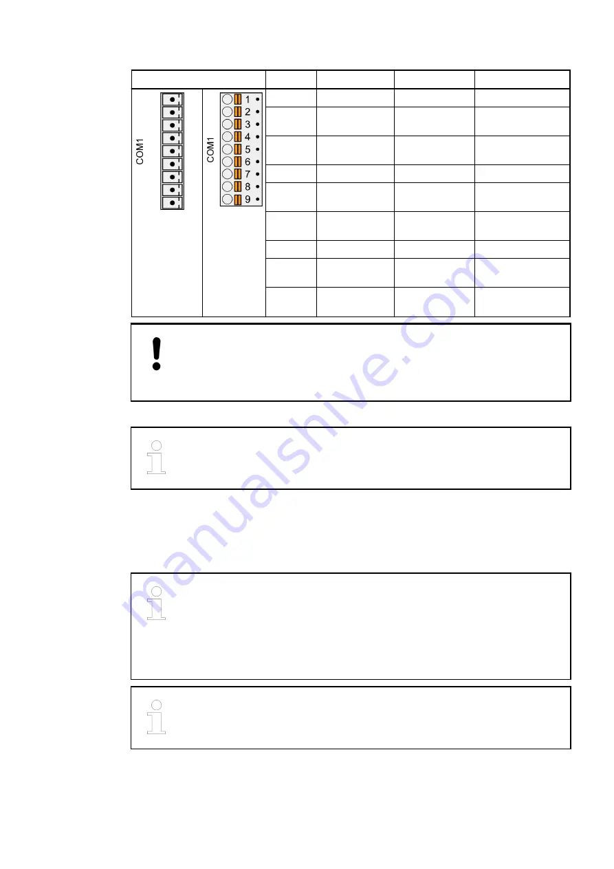
Pin
Signal
Interface
Description
Terminal
block
removed
Terminal
block
inserted
1
Terminator P
RS-485
Terminator P
2
RxD/TxD-P
RS-485
Receive/Transmit,
positive
3
RxD/TxD-N
RS-485
Receive/Transmit,
negative
4
Terminator N
RS-485
Terminator N
5
RTS
RS-232
Request to send
(output)
6
TxD
RS-232
Transmit data
(output)
7
SGND
Signal Ground
Signal Ground
8
RxD
RS-232
Receive data
(input)
9
CTS
RS-232
Clear to send
(input)
NOTICE!
Unused connector!
Make sure that the terminal block is always connected to the terminal base or
communication module, even if you do not use the interface.
For further information on connection and wiring please refer to .
1.2.1.2.4 Ethernet interface
This interface is the connection to a processor module with onboard Ethernet e.g.
PM56xx-2ETH.
TB56xx-2ETH for processor modules PM56xx-2ETH provide 2 independent
Ethernet interfaces.
The two Ethernet interfaces can be configured as independent interfaces or with
switch functionality.
In case of two independent interfaces they must be configured to different
subnets.
For structured Ethernet cabling only use cables according to TIA/EIA-568-A,
ISO/IEC 11801 or EN 50173.
Pin assignment
(RS-485 /
RS-232)
Device specifications
Terminal bases (AC500 standard) > TB56xx for AC500 V3 products
2022/01/31
3ADR010278, 3, en_US
9