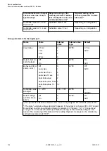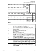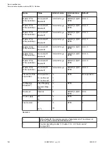
Parameter
Value
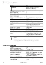
Reference potential for AO0+ to AO1+
Terminal 1.7 (AO-) for voltage outputTerminal
1.9, 2.9 and 3.9 for current output
Output type
Unipolar
Current
Bipolar
Voltage
Galvanic isolation
Against internal supply and other modules
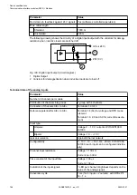
Configurability
-10...+10 V, 0...20 mA, 4...20 mA (each output
can be configured individually)
Output resistance (load), as current output
0...500
W
Output loadability, as voltage output
±
10 mA max.
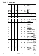
Indication of the output signals
1 LED per channel (brightness depends on the
value of the analog signal)
Resolution
12 bits (+ sign)
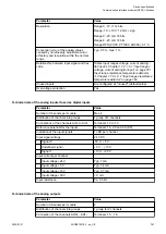
Settling time for full range change (resistive
load, output signal within specified tolerance)
Typ. 5 ms
Conversion error of the analog values
caused by non-linearity, adjustment error
at factory and resolution within the normal
range
Typ. 0.5 %, max. 1 %
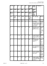
Relationship between input signal and hex
code
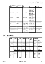
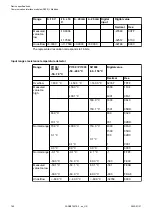
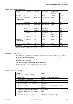
Table Output ranges voltage and current
Chapter 1.7.4.1.9.3 “Output ranges voltage
Unused outputs
Are configured as "unused" (default value) and
can be left open-circuited
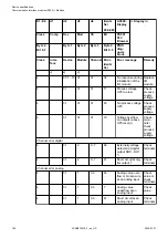
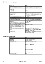
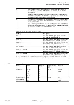
Technical data of the fast counter
Parameter
Value
Used inputs
Terminal 2.0 (DI0), 2.1 (DI1)
Used outputs
Terminal 3.0 (DO0)
Counting frequency
Depending on operation mode:
Mode 1 - 6: max. 200 kHz
Mode 7: max. 50 kHz
Mode 9: max. 35 kHz
Mode 10: max. 20 kHz
Detailed description
See
Device specifications
Communication interface modules (S500) > Modbus
2022/01/31
3ADR010278, 3, en_US
768

