


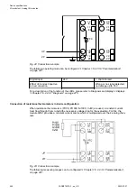
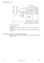
The function of the LEDs is described under Diagnosis and displays / displays
1.6.2.2.3.7 “Diagnosis” on page 475
In order to avoid error messages or long processing times, it is useful to configure unused
analog input channels as "unused".
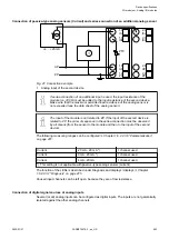
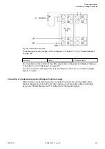
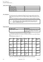
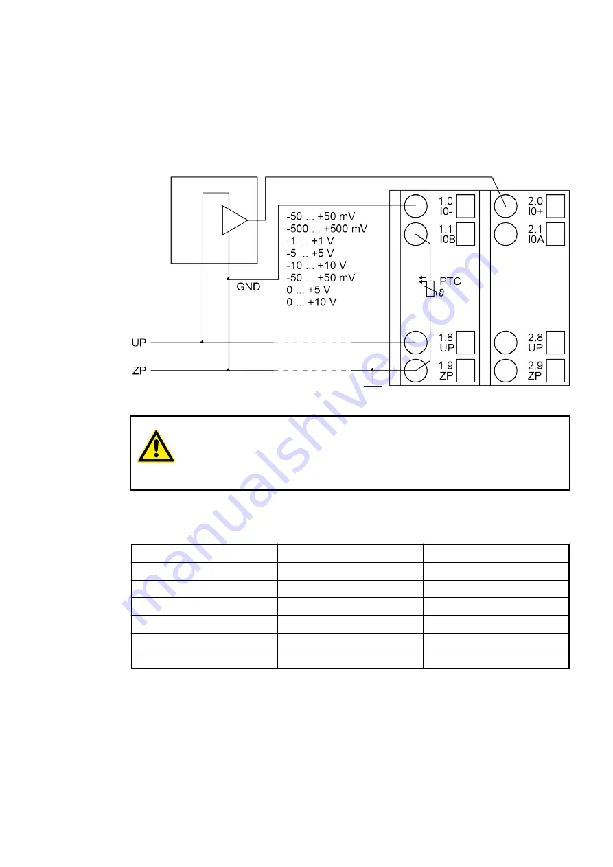
Connection of active-type analog sensors (Voltage) with no galvanically isolated power supply
Fig. 36: Connection example
CAUTION!
If GND is not directly connected to ZP at the sensor, the supply current flows
via the GND line to ZP. Measuring errors can only occur caused by voltage
differences higher than
±
20 V DC between GND and ZP.
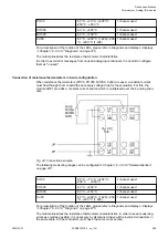
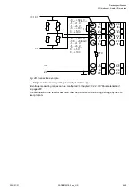
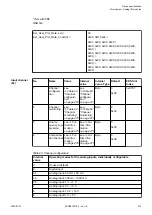
The measuring ranges can be configured
Chapter 1.6.2.2.3.6 “Parameterization”
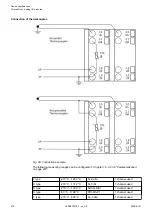
Voltage
-50 mV...+50 mV
1 channel used
Voltage
-500 mV...+500 mV
1 channel used
Voltage
-1 V...+1 V
1 channel used
Voltage
-5 V...+5 V
1 channel used
Voltage
-10 V...+10 V
1 channel used
Voltage
0 V...+5 V
1 channel used
Voltage
0 V...+10 V
1 channel used
Standard ranges
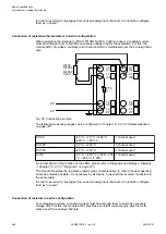
Device specifications
I/O modules > Analog I/O modules
2022/01/31
3ADR010278, 3, en_US
459