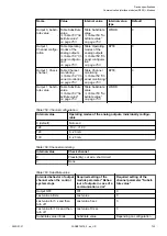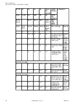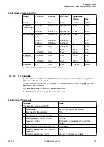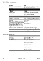
Intended behavior of output
channel when the control
system stops
Required setting of the
module parameter "Behav-
iour of outputs in case of a
communication error"
Required setting of the
channel parameter "Substi-
tute value"
Substitute value for 5 s and
then turn off
Substitute value 5 sec
Depending on configuration
Substitute value for 10 s and
then turn off
Substitute value 10 sec
Depending on configuration
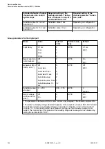
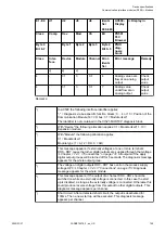
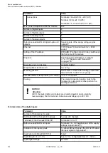
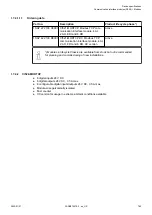
Group parameters for the digital part
Name
Value
Internal
value
Internal value,
type
Default
Input delay
0.1 ms
1 ms
8 ms
32 ms
0
1
2
3
BYTE
0.1 ms
0x00
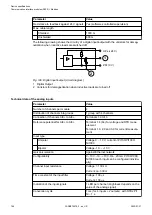
Detect short cir-
cuit at outputs
Off
On
0
1
BYTE
On
0x01
Behaviour DO at
comm. error
1
)
Off
Last value
Last value 5 sec
Last value 10 sec
Substitute value
Substitute value 5 sec
Substitute value 10
sec
0
1
6
11
2
7
12
BYTE
Off
0x00
Substitute value
at output
0 ... 255
00h ... FFh
BYTE
0
0x0000
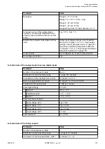
Detect voltage
overflow at out-
puts
2
)
Off
On
0
1
BYTE
On
0x01
1
) The parameters Behaviour DO at comm. error is only analyzed if the Failsafe-mode is ON.
2
) The state "externally voltage detected" appears, if the output of a channel DC0..DC7 should
be switched on while an externally voltage is connected
Chapter 1.7.4.1.3 “Connections”
. In this case the start up is disabled, as long as the externally voltage is con-
nected. The monitoring of this state and the resulting diagnosis message can be disabled by
setting the parameters to "OFF".
Device specifications
Communication interface modules (S500) > Modbus
2022/01/31
3ADR010278, 3, en_US
754


