


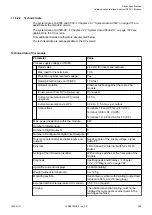


1.7.4.2.9 Technical data
The system data of AC500 and S500
Chapter 2.6.1 “System data AC500” on page 971
are
applicable to the standard version.
The system data of AC500-XC
Chapter 2.7.1 “System data AC500-XC” on page 1023
applicable to the XC version.
Only additional details are therefore documented below.
The technical data are also applicable to the XC version.
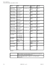
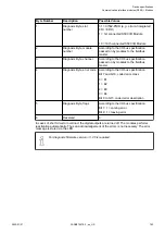
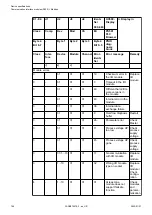
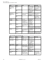
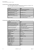
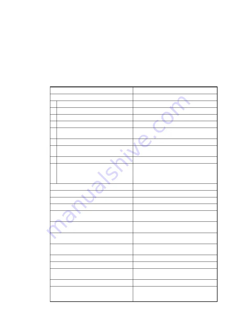
Technical data of the module
Parameter
Value
Process supply voltages UP/UP3
Rated value
24 V DC (for inputs and outputs)
Max. load for the terminals
10 A
Protection against reversed voltage
Yes
Rated protection fuse on UP/UP3
10 A fast
Galvanic isolation
Ethernet interface against the rest of the
module
Inrush current from UP (at power up)
On request
Current consumption via UP (normal
operation)
0.15 A
Current consumption via UP3
0.06 A + 0.5 A max. per output
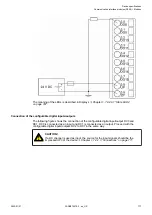
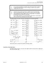
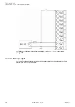
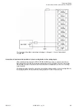
Connections
Terminals 1.8 and 2.8 for +24 V (UP)
Terminal 3.8 for +24 V (UP3)
Terminals 1.9, 2.9 and 3.9 for 0 V (ZP)
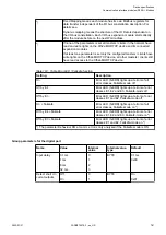
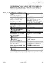
Max. power dissipation within the module
6 W
Number of digital inputs
8
Number of digital outputs
8
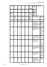
Number of configurable digital inputs/outputs
8
Reference potential for all digital inputs and
outputs
Negative pole of the supply voltage, signal
name ZP
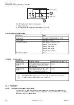
Ethernet
10/100 base-TX, internal switch, 2 x RJ45
socket
Setting of the I/O device identifier
With 2 rotary switches at the front side of the
module
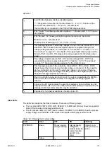
Diagnosis
See Diagnosis and Displays
1.7.4.2.8 “Diagnosis” on page 782
Operation and error displays
34 LEDs (totally)
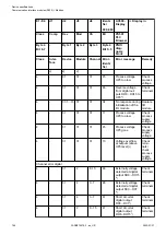
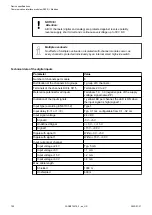
Weight (without terminal unit)
Ca. 125 g
Mounting position
Horizontal or vertical with derating (output load
reduced to 50 % at 40°C per group)
Extended ambient temperature (XC version)
> 60 °C on request
Cooling
The natural convection cooling must not be
hindered by cable ducts or other parts in the
switchgear cabinet.
Device specifications
Communication interface modules (S500) > Modbus
2022/01/31
3ADR010278, 3, en_US
789