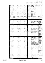
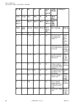
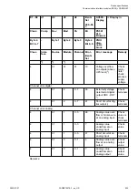

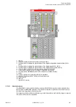


1
I/O bus
2
Allocation between terminal number and signal name
3
8 yellow LEDs to display the signal states of the digital configurable inputs/outputs (DC0 -
DC7)
4
8 yellow LEDs to display the signal states of the digital inputs (DI8 - DI15)
5
8 yellow LEDs to display the signal states of the digital outputs (DO8 - DO15)
6
2 green LEDs to display the process supply voltage UP and UP3
7
3 red LEDs to display errors (CH-ERR1, CH-ERR2, CH-ERR3)
8
5 system LEDs: PWR/RUN, STA1 ETH, STA2 ETH, S-ERR, I/O-Bus
9
Label
10 2 rotary switches for setting the I/O device identifier
11 Ethernet interfaces (ETH1, ETH2) on the terminal unit
12 Terminal unit
13 DIN rail
Sign for XC version
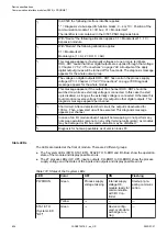
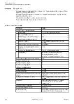
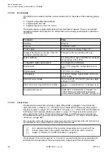
1.7.5.3.1 Intended purpose
The PROFINET communication interface module CI502-PNIO is used as communication inter-
face module in PROFINET networks. The network connection is performed via 2 RJ45 connec-
tors which are integrated in the terminal unit.
For usage in extreme ambient conditions (e.g. wider temperature and humidity range), a special
XC version of the device is available.
Device specifications
Communication interface modules (S500) > PROFINET
2022/01/31
3ADR010278, 3, en_US
837