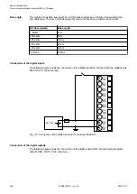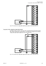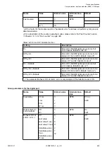
*) Modules in lifecycle Classic are available from stock but not recommended
for planning and commissioning of new installations.
1.7.2.3
CI582-CN
● 8 digital inputs 24 V DC
● 8 digital outputs 24 V DC, 0.5 A max.
● 8 configurable digital inputs/outputs 24 V DC, 0.5 A max.
● Module-wise galvanically isolated
● Fast counter
● XC version for use in extreme ambient conditions available
3.0
3.1
3.2
3.3
3.4
3.5
3.6
3.7
3.8
3.9
2.0
2.1
2.2
2.3
2.4
2.5
2.6
2.7
2.8
2.9
1.0
1.1
1.2
1.3
1.4
1.5
1.6
1.7
1.8
1.9
4.0
4.1
4.2
4.3
4.4
4.5
4.6
4.7
4.8
4.9
CI582
CH-ERR1
CH-ERR3
CH-ERR2
UP 24VDC 100W
CANopen Slave
4AI 2AO 8DI 8DO
Input 24VDC/Output 24VDC 0.5A
PWR/
RUN
ADDR x01H
ADDR x10H
4
C
3
B
2
A
1
9
0
8
F
7
E
6
D
5
4
C
3
B
2
A
1
9
0
8
F
7
E
6
D
5
1.8GND
1.9GND
1.0 CAN+
1.2 CAN-
1.3CAN-
1.5 Term+
1.6 Term-
1.4 Term+
1.7 Term-
1.1 CAN+ CN-
RUN
CN-
ERR
S-
ERR
I/O-
Bus
2.0 DC0
2.2 DC2
2.9 ZP
2.3 DC3
2.1 DC1
2.5 DC5
2.6 DC6
2.8 UP
2.7 DC7
2.4 DC4
3.8 UP
3.9 ZP
3.0 DI8
3.2 DI10
3.3 DI11
3.5 DI13
3.6 DI14
3.4 DI12
3.7 DI15
3.1 DI9
4.0 DO8
4.2 DO10
4.4 DO12
4.6 DO14
4.9 ZP
4.1 DO9
4.3 DO11
4.5 DO13
4.7 DO15
4.8 UP3
1
2
3
4
5
6
7
8
9
10
12
13
11
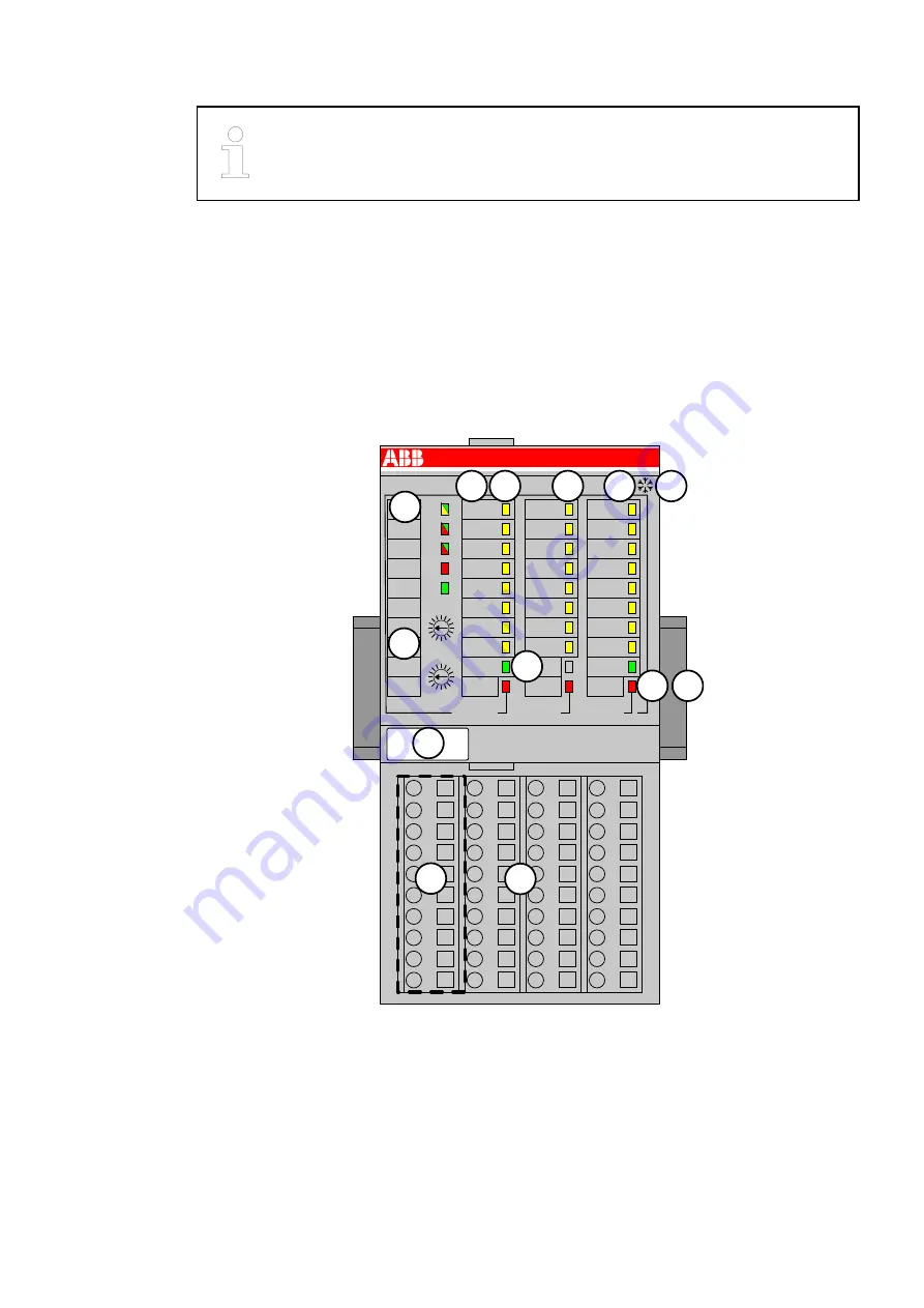
1
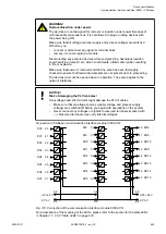
I/O bus
2
Allocation between terminal number and signal name
3
8 yellow LEDs to display the signal states of the configurable digital inputs/outputs (DC0 -
DC7)
4
8 yellow LEDs to display the signal states of the digital inputs (DI8 - DI15)
5
8 yellow LEDs to display the signal states of the digital outputs (DO8 - DO15)
6
2 green LEDs to display the supply voltage UP and UP3
7
3 red LEDs to display errors (CH-ERR1, CH-ERR2, CH-ERR3)
8
5 System LEDs: PWR/RUN, CN-RUN, CN-ERR, S-ERR, I/O-Bus
9
Label
10 2 rotary switches for setting the CANopen node ID
Device specifications
Communication interface modules (S500) > CANopen
2022/01/31
3ADR010278, 3, en_US
657


