

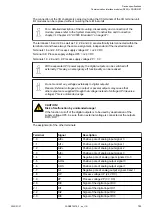

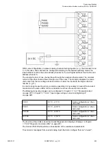
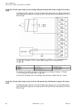
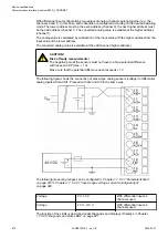
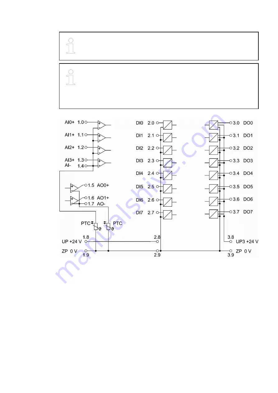
For the open-circuit detection (cut wire), each analog input channel is pulled up
to "plus" by a high-resistance resistor. If nothing is connected, the maximum
voltage will be read in then.
Generally, analog signals must be laid in shielded cables. The cable shields
must be grounded at both sides of the cables. In order to avoid unacceptable
potential differences between different parts of the installation, low resistance
equipotential bonding conductors must be laid.
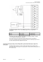
Only for simple applications (low electromagnetic disturbances, no high require-
ment on precision), the shielding can also be omitted.
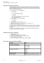
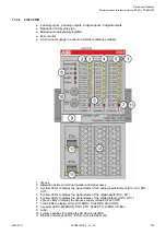
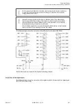
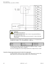
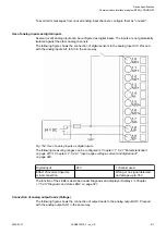
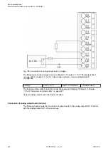
The following figures show the connection of the Ethernet bus module CI501-PNIO.
Further information is provided in the System Technology chapter .
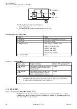
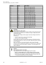
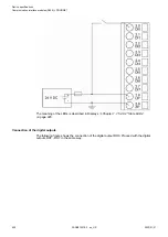
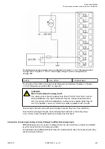
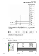
Connection of the digital inputs
The following figure shows the connection of the digital input DI0. Proceed with the digital inputs
DI1 to DI7 in the same way.
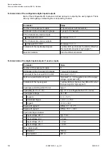
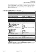
Device specifications
Communication interface modules (S500) > PROFINET
2022/01/31
3ADR010278, 3, en_US
801