1.8
1.9
UP
ZP
UP
ZP
1.5
1.7
1.6
AO1+
AO0+
AO–
–10 V...+10 V
0...20 mA
4...20 mA
1
1.9
ZP
1.7
AO–
PTC
2
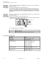
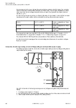
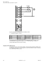
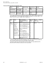
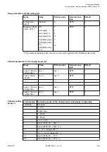
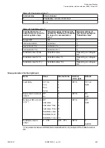
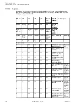
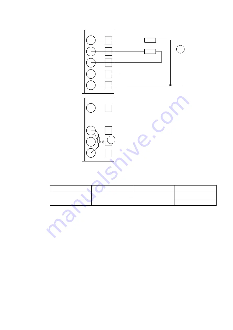
Fig. 131: Connection of analog output loads (voltage, current)
1
1 analog load requires 1 channel
Voltage
-10 V...+10 V
Load ±10 mA max.
1 channel used
Current
0...20 mA
Load 0...500 Ω
1 channel used
Current
4...20 mA
Load 0...500 Ω
1 channel used
The measuring ranges are described in the section Measuring Ranges
“Parameterization” on page 694
Chapter 1.7.3.1.10 “Measuring ranges” on page 703
.
Unused analog outputs can be left open-circuited.
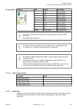
Assignment of the Ethernet ports
The terminal unit for the communication interface module provides two Ethernet interfaces with
the following pin assignment. The pin assignment is used for the EtherCAT master (communica-
tion module CM5xy-ETHCAT) as well.
Device specifications
Communication interface modules (S500) > EtherCAT
2022/01/31
3ADR010278, 3, en_US
692

