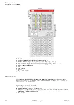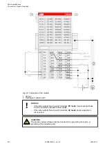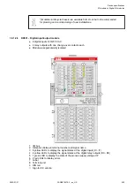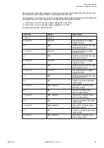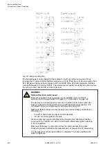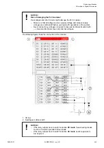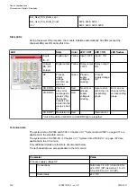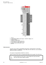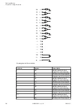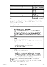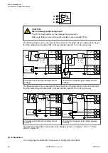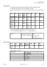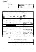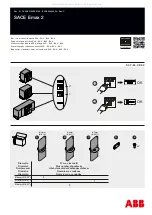
The connection of the I/O channels is carried out using the 40 terminals of the I/O terminal unit.
I/O modules can be replaced without re-wiring the terminal units.
The terminals 1.8 to 4.8 and 1.9 to 4.9 are electrically interconnected within the I/O terminal unit
and always have the same assignment, irrespective of the inserted module:
● Terminals 1.8 to 4.8: process supply voltage UP = +24 V DC
● Terminals 1.9 to 4.9: process supply voltage ZP = 0 V DC
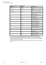
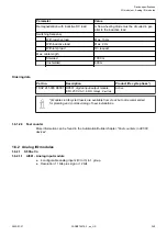
The assignment of the other terminals:
Terminals
Signal
Description
1.0 to 1.7
unused
2.0 and 3.0
I0 and I1
Input signals for the digital
inputs I0 and I1
4.0
N01
Neutral conductor for the dig-
ital inputs I0 and I1
2.1 and 3.1
I2 and I3
Input signals for the digital
inputs I2 and I3
4.1
N23
Neutral conductor for the dig-
ital inputs I2 and I3
2.2 and 3.2
I4 and I5
Input signals for the digital
inputs I4 and I5
4.2
N45
Neutral conductor for the dig-
ital inputs I4 and I5
2.3 and 3.3
I6 and I7
Input signals for the digital
inputs I6 and I7
4.3
N67
Neutral conductor for the dig-
ital inputs I6 and I7
2.4
R0
Common contact of the first
relay output
3.4 and 4.4
NO0 and NC0
NO and NC contacts of the
first relay output
2.5
R1
Common contact of the
second relay output
3.5 and 4.5
NO1 and NC1
NO and NC contacts of the
second relay output
2.6
R2
Common contact of the third
relay output
3.6 and 4.6
NO2 and NC2
NO and NC contacts of the
third relay output
2.7
R3
Common contact of the fourth
relay output
3.7 and 4.7
NO3 and NC3
NO and NC contacts of the
fourth relay output
Device specifications
I/O modules > Digital I/O modules
2022/01/31
3ADR010278, 3, en_US
341

