
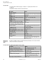


Technical data
The System Data of AC500-eCo apply
Chapter 2.5.1 “System data AC500-eCo V3”
Only additional details are therefore documented below.
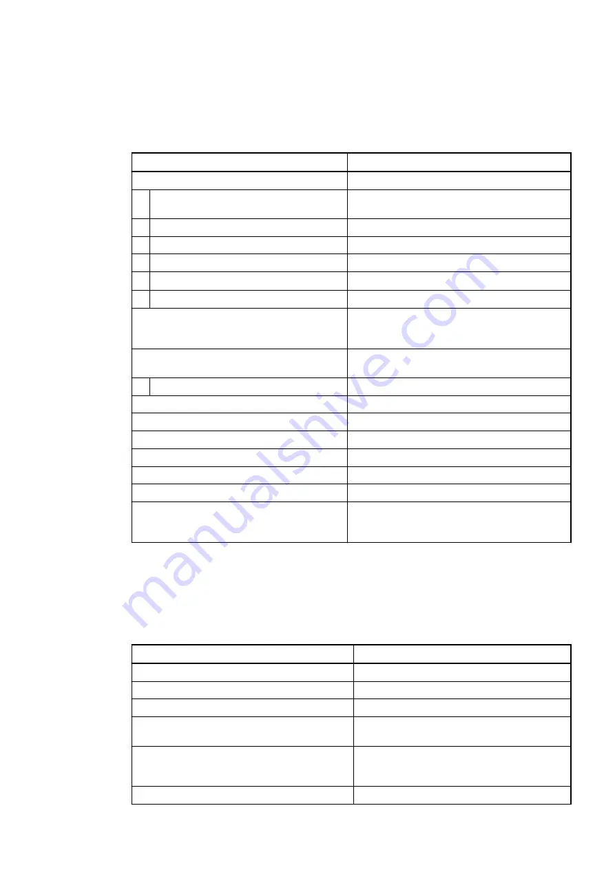
Parameter
Value
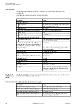
Process voltage UP
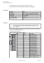
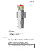
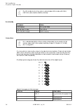
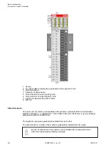
Connections
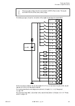
Terminal 19 for UP (+24 V DC) and terminal 20
for ZP (0 V)
Rated value
24 V DC
Current consumption via UP terminal
90 mA + 0.5 A per output (max.)
Max. ripple
5 %
Inrush current
0.000001 A
2
s
Protection against reversed voltage
Yes
Current consumption from 24 V DC power
supply at the L+/UP and M/ZP terminals of
the CPU/communication interface module
Ca. 10 mA
Galvanic isolation
Yes, between the input/output group and the
rest of the module
Isolated groups
1 group for 16 channels
Surge voltage (max.)
35 V DC for 0.5 s
Max. power dissipation within the module
4.8 W
Input data length
2 bytes
Output data length
2 bytes
Weight
Ca. 125 g
Mounting position
Horizontal or vertical
Cooling
The natural convection cooling must not be
hindered by cable ducts or other parts in the
switchgear cabinet.
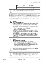
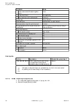
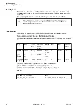
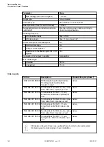
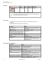
No effects of multiple overloads on isolated multi-channel modules occur, as every channel is
protected individually by an external fuse.
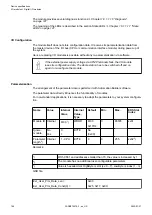
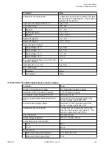
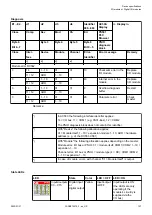
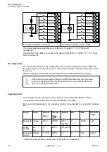
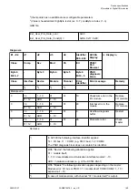
Technical data of the digital inputs/outputs if used as inputs
Parameter
Value
Number of channels per module
16 configurable inputs (24 V DC)
Distribution of the channels into groups
1 (16 channels per group)
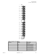
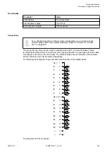
Connections of the channels C0 to C15
Terminals 1 to 16
Reference potential for the channels C0 to
C15
Terminal 20 (negative pole of the process
voltage, name ZP)
Indication of the input signals
1 yellow LED per channel; the LED is ON
when the input signal is high (signal 1). The
module is powered through the I/O bus.
Input type according to EN 61131-2
Type 1 sink
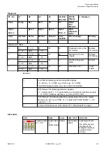
No effects of
multiple over-
loads
Device specifications
I/O modules > Digital I/O modules
2022/01/31
3ADR010278, 3, en_US
158