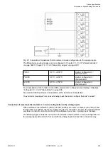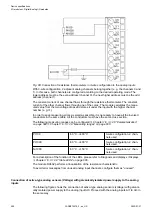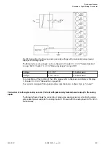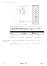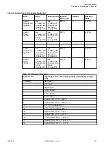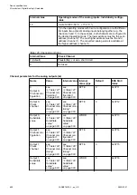
Table 127: Channel configuration
Internal value
Operating modes of the analog outputs, individually configu-
rable
0 (default)
Not used
128
-10 V...+10 V
129
0 mA...20 mA
130
4 mA...20 mA
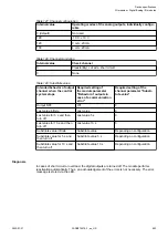
Table 128: Channel monitoring
Internal value
Check channel
0
Plausib(ility), cut wire, short circuit
3
None
Table 129: Substitute value
Intended behavior of output
channel when the control
system stops
Required setting of
the module parameter
"Behavior of outputs in
case of a communication
error"
Required setting of the
channel parameter "Substi-
tute value"
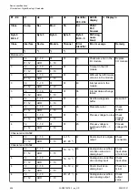
Output OFF
Off
0
Last value infinite
Last value
0
Last value for 5 s and then
turn off
Last value 5 s
0
Last value for 10 s and then
turn off
Last value 10 s
0
Substitute value infinite
Substitute value
Depending on configuration
Substitute value for 5 s and
then turn off
Substitute value 5 s
Depending on configuration
Substitute value for 10 s and
then turn off
Substitute value 10 s
Depending on configuration
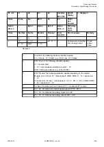
Diagnosis
In cases of short circuit or overload, the digital outputs are turned off. The module performs
reactivation automatically. Thus, an acknowledgement of the errors is not necessary. The error
message is stored via the LED.
Device specifications
I/O modules > Digital/Analog I/O modules
2022/01/31
3ADR010278, 3, en_US
603

