


1.0
1.1
1.8
1.9
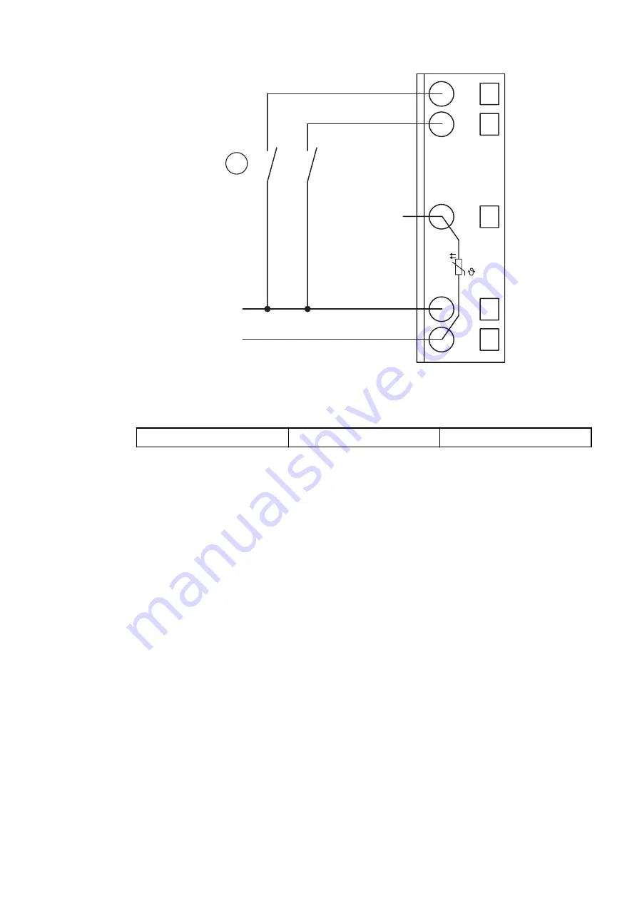
AI0+
AI1+
UP
ZP
UP
ZP
PTC
1.5
AI–
1
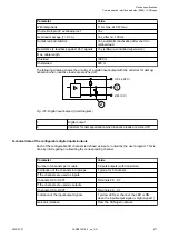
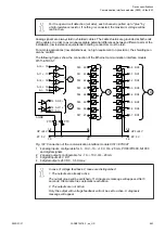
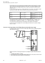
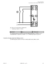
Fig. 130: Use of analog inputs as digital inputs
1
1 digital signal requires 1 channel
Digital input
24 V
1 channel used
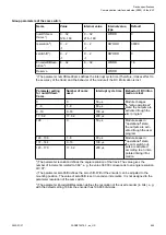
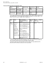
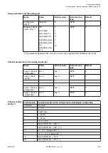
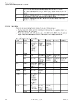
The measuring ranges are described in the section Measuring Ranges
“Parameterization” on page 694
Chapter 1.7.3.1.10 “Measuring ranges” on page 703
.
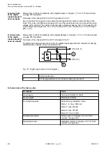
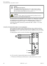
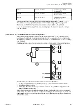
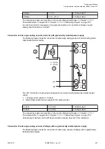
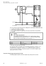
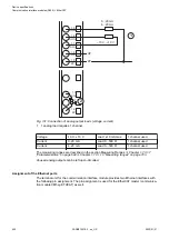
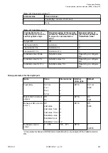
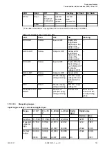
Connection of analog output loads (Voltage, current)
The following figure shows the connection of analog output loads (voltage, current).
Device specifications
Communication interface modules (S500) > EtherCAT
2022/01/31
3ADR010278, 3, en_US
691