background image

/REV1

Operating Instructions No. 246 (EN)

D

evice:

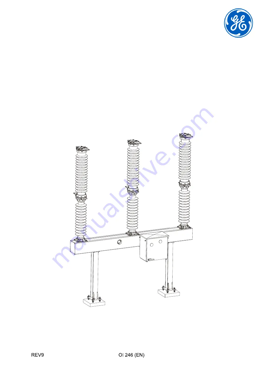
High Voltage Circuit Breaker
GL 310 F1/4031 P/VR         GL310 F1/4040 P/VR
GL 311 F1/4031 P/VR         GL311 F1/4040 P/VR
GL 312 F1/4031 P/VR         GL312 F1/4040 P/VR
GL 313 F1/4031 P/VR

Manufacturer: GE Grid GmbH

Lilienthalstrasse 150 - 34123 Kassel, Germany

B

A

-P

-S

C

H

A

L

T

E

R

-T

IT

E

L

Summary of Contents for GL 310 F1/4031 P/VR

Page 1: ...Voltage Circuit Breaker GL 310 F1 4031 P VR GL310 F1 4040 P VR GL 311 F1 4031 P VR GL311 F1 4040 P VR GL 312 F1 4031 P VR GL312 F1 4040 P VR GL 313 F1 4031 P VR Manufacturer GE Grid GmbH Lilienthalst...

Page 2: ......

Page 3: ...4 6 4 Unpacking the Transport Units 24 6 4 1 Base Frame 25 6 4 2 Pole Column 25 6 4 2 a Unpacking Pole Column with Composite Insulators 27 6 4 2 b Unpacking Pole Column with Porcelain Insulators 28 6...

Page 4: ...ng System 63 7 6 8 Checking the Functional Lockout 63 7 6 9 Operations Counter 63 7 6 10 Final Tasks 63 8 Troubleshooting 65 8 1 Electrical Switching Commands Are Not Correctly Executed 65 8 2 Mechani...

Page 5: ...ecting the Interrupter Chamber to the Post Insulator 97 10 1 14 Replacing the Adsorption filter 99 10 1 15 Final Operations 100 10 2 Disassembling the Post Insulator and Crankcase 100 10 2 1 Disassemb...

Page 6: ...ing 125 A2 9 Auxiliary Materials and Supplies 126 A3 Replacement Parts and Accessories 127 A3 1 Servicing Equipment 128 A3 2 Replacement of Arcing Contacts 129 A3 3 Replacement Parts for Installation...

Page 7: ...INTRODUCTION REV6 7 1 Introduction GE Grid GmbH Lilienthalstrasse 150 34123 Kassel Germany Telephone 49 561 502 0 Fax 49 561 502 2499...

Page 8: ...INTRODUCTION 8 REV6 Copyright Notice Trademark Notices...

Page 9: ...INTRODUCTION REV6 9...

Page 10: ...INTRODUCTION 10 REV6...

Page 11: ...SAFETY REV3 11 2 Safety 2 1 Safety Instructions DANGER WARNING CAUTION CAUTION...

Page 12: ...SAFETY 12 REV3...

Page 13: ...HANDLING SULFUR HEXAFLUORIDE REV3 13 3 Handling Sulfur Hexafluoride Standards governing SF6 handling 3 1 Safety Precautions When Handling SF6 3 1 1 Oxygen Displacement 3 1 2 Mechanical Handling...

Page 14: ...HANDLING SULFUR HEXAFLUORIDE 14 REV3 3 1 3 Frostbite WARNING...

Page 15: ...HANDLING SULFUR HEXAFLUORIDE REV3 15 3 2 Safety Precautions When Handling Used SF6 WARNING...

Page 16: ...HANDLING SULFUR HEXAFLUORIDE 16 REV3 3 3 Transport at the Installation Site CAUTION Therefore Do not move pole columns if the gas gauge pressure is higher than the shipping pressure DANGER...

Page 17: ...COMPONENTS SUPPLIED REV1 17 4 Components Supplied 4 1 Scope of Supply Standard...

Page 18: ...COMPONENTS SUPPLIED 18 REV1 4 2 Scope of Supply Optional...

Page 19: ...AGE REV1 19 5 Transport and Storage 5 1 Transport and Handling Therefore Comply with handling markings and labeling Use hoisting equipment with adequate load bearing capacity Do not stand under suspen...

Page 20: ...TRANSPORT AND STORAGE 20 REV1 5 2 Storage CAUTION...

Page 21: ...INSTALLATION REV6 21 6 Installation 6 1 Preparing for Installation 6 1 1 Documentation 6 1 2 Checklist...

Page 22: ...INSTALLATION 22 REV6 Checklist for Installation and Commissioning Circuit Breaker Data Type Serial No Customer Station Installation No Operation to Be Performed Section...

Page 23: ...23 Checklist for Installation and Commissioning Fax 49 561 502 2774 E Mail checkliste kassel alstom com Circuit Breaker Data Type Serial No Customer Station Commissioning No Operation to Be Performed...

Page 24: ...Provided by Customer 6 3 Use of Auxiliary Materials and Supplies 6 4 Unpacking the Transport Units Therefore Comply with handling markings and labeling Use hoisting equipment with adequate load beari...

Page 25: ...REV6 25 6 4 1 Base Frame 6 4 2 Pole Column composite or porcelain insulators Composite insulators Porcelain insulators Therefore Clean and wash the silicone shielding using only water or isopropyl alc...

Page 26: ...all present persons must take cover or comply with the following minimum distance for porcelain insulators approx 50 m for composite insulators the height of the device measured from ground level to...

Page 27: ...h lifting tackle solely to the fastening points provided on the lower post insulator flange and the upper terminal pad mounting plate CAUTION Therefore Select squared timbers of sufficient height and...

Page 28: ...8 REV6 6 4 2 b Unpacking Pole Column with Porcelain Insulators Therefore Select squared timbers of sufficient height and position them correctly in order to prevent the insulators from tou ching the g...

Page 29: ...the SF6 Shipping Pressure Procedure for using the shipping pressure indicator Evaluating the indication Therefore Do not use the shipping pressure indicator to check rated pressures alarm pressures o...

Page 30: ...INSTALLATION 30 REV6 6 4 3 Operating Mechanism 2 T116 3 1...

Page 31: ...INSTALLATION REV6 31 6 5 Preinstalling the Supports...

Page 32: ...INSTALLATION 32 REV6 6 6 Installing the Base Frame see Preinstalling the Supports on Page 31...

Page 33: ...INSTALLATION REV6 33 6 7 Installing the Mechanism Brackets...

Page 34: ...Never operate the mechanism without the pole columns CAUTION Therefore The operating mechanism must be completely discharged during installation The position indications must be as follows Closing sp...

Page 35: ...INSTALLATION REV6 35...

Page 36: ...INSTALLATION 36 REV6...

Page 37: ...6 9 1 Erecting the Pole Columns CAUTION 3 2 1 S S Therefore Never lift the pole columns from the high voltage terminal pads attached to the pole column Always use the holes in the terminal pad mounti...

Page 38: ...INSTALLATION 38 REV6 6 9 2 Positioning the Pole Columns...

Page 39: ...INSTALLATION REV6 39...

Page 40: ...INSTALLATION 40 REV6 6 10 Aligning and Connecting the Pole Columns...

Page 41: ...INSTALLATION REV6 41 6 11 Aligning and Connecting Pole Column B Therefore Do not change the rod length Never use a drive rod with a different breaker serial number CAUTION...

Page 42: ...INSTALLATION 42 REV6 6 11 1 Connecting the Drive Rod to the Drive Lever...

Page 43: ...INSTALLATION REV6 43 6 11 2 Connecting the Drive Rod to Pole B...

Page 44: ...INSTALLATION 44 REV6...

Page 45: ...INSTALLATION REV6 45 6 11 3 Connecting the Lever to the Connecting Rod for Pole C...

Page 46: ...INSTALLATION 46 REV6 6 11 4 Aligning and Connecting Pole Column A...

Page 47: ...INSTALLATION REV6 47 6 11 5 Aligning and Connecting Pole Column C...

Page 48: ...INSTALLATION 48 REV6 6 12 Mounting the High Voltage Terminal Pads...

Page 49: ...INSTALLATION REV6 49 6 13 Connecting the Cables Therefore The cables may only be connected by qualified personnel using extreme caution DANGER DANGER...

Page 50: ...INSTALLATION 50 REV6 6 14 Earthing Grounding the Circuit Breaker...

Page 51: ...V7 51 7 Commissioning 7 1 Density Monitor 7 1 1 Connecting the Cable Therefore Make sure that the circuit breaker is disconnected from the high voltage system Make sure the circuit breaker is earthed...

Page 52: ...COMMISSIONING 52 REV7 7 1 2 Checking the Operating Points of the density monitor EasyCheck EasyCheck F gases regulation EU 517 2014 see EasyCheck Density Monitor Unit on Page 107 Caution...

Page 53: ...COMMISSIONING REV7 53 Instruction D...

Page 54: ...ity on Page 79 Therefore Inspect the pole columns visually for damage before be ginning the filling operation Carry out the filling operation from a protected position WARNING Therefore Never set the...

Page 55: ...COMMISSIONING REV7 55 7 2 1 Establish Gas Connections between Density Monitor and Pole columns FlexLink FlexLink see FlexLink Gas Connection on Page 111...

Page 56: ...COMMISSIONING 56 REV7 7 3 Filling the Breaker with Gas CAUTION t C p_rel bar...

Page 57: ...COMMISSIONING REV7 57 t C p_rel bar...

Page 58: ...les Therefore Make sure the supply and control cables are not live befo re connecting them WARNING Therefore Keep parts of the body and other objects away from the moving parts of the operating mechan...

Page 59: ...efore Never operate the circuit breaker at gas pressures below UW2 red area on the density monitor indicator CAUTION Therefore Always carry out test operations from a protected positi on WARNING There...

Page 60: ...REV7 7 6 3 Measuring the Contact Resistance high voltage terminal pads terminal pad mounting plate see Mounting the High Voltage Ter minal Pads on Page 48 7 6 4 Measuring the Operating Times Closing t...

Page 61: ...COMMISSIONING REV7 61 7 6 5 Checking Manual Operation Therefore Make sure that the gas pressure in the circuit breaker cor responds at least to the UW2 value before beginning ma nual operation WARNING...

Page 62: ...COMMISSIONING 62 REV7 7 6 6 Manually Charging the Closing Spring...

Page 63: ...IONING REV7 63 7 6 7 Checking the Anti Pumping System Type with Closing Priority Standard Type with Opening Priority Optional 7 6 8 Checking the Functional Lockout 7 6 9 Operations Counter 7 6 10 Fina...

Page 64: ...COMMISSIONING 64 REV7...

Page 65: ...TROUBLESHOOTING REV2 65 8 Troubleshooting 8 1 Electrical Switching Commands Are Not Correctly Executed DANGER...

Page 66: ...66 REV2 8 2 Mechanism Reconditioning Procedures 8 2 1 Replacing the Charging Motor CAUTION If this is not the case Turn off the power to the motor immediately Check the connections and correct if nec...

Page 67: ...TROUBLESHOOTING REV2 67 8 2 2 Replacing the Closing and Opening Coil Make sure you have the correct coil type Compare the part number on the coils CAUTION...

Page 68: ...TROUBLESHOOTING 68 REV2 8 2 3 Replacing the Operations Counter...

Page 69: ...TROUBLESHOOTING REV2 69 8 2 4 Replacing the Motor Limit Switch and or the Auxiliary Switch...

Page 70: ...TROUBLESHOOTING 70 REV2 Motor limit switch Auxiliary switch CAUTION...

Page 71: ...TROUBLESHOOTING REV2 71 8 3 Replacing the Density Monitor left hand thread left hand thread EasyCheck EasyCheck F gases regulation EU 517 2014 Siehe EasyCheck Density Monitor Unit auf Seite 107...

Page 72: ...TROUBLESHOOTING 72 REV2...

Page 73: ...TROUBLESHOOTING REV2 73 8 3 1 Austausch einer Gasverbindung FlexLink FlexLink Siehe FlexLink Gas Connection auf Seite 111...

Page 74: ...TROUBLESHOOTING 74 REV2...

Page 75: ...INSPECTION AND MAINTENANCE REV3 75 9 Inspection and Maintenance Therefore Clean and wash the silicone shielding using only water or isopropyl alcohol CAUTION CAUTION...

Page 76: ...INSPECTION AND MAINTENANCE 76 REV3 CAUTION 40 2500 3 15 15 n I kA...

Page 77: ...tion 9 2 2 Anti Condensation Heater 9 2 3 Checking Gas Pressure see Filling the Breaker with Gas on Page 56 Therefore Never reach into the high voltage insulation area of the circuit breaker Never tou...

Page 78: ...the Control Circuits see Test Operations on Page 59 Breaker Position State of the Closing Spring Operations to Be Executed Therefore Disconnect the breaker from the high voltage system and ground ear...

Page 79: ...ND MAINTENANCE REV3 79 9 3 4 Checking the Gas Quality see Tools and Auxiliary Equipment on Page 119 9 3 5 Checking the Contact Resistance 9 3 6 Checking the Operating Times 9 3 7 Checking the Threaded...

Page 80: ...INSPECTION AND MAINTENANCE 80 REV3...

Page 81: ...e breaker from the high voltage system and ground earth the breaker at both ends DANGER Therefore Discharge the closing and opening springs by carrying out closing and opening operations DANGER Breake...

Page 82: ...sconnecting the Interrupter Chamber from the Post Insulator see Slow Operation for Maintenance Purposes on Page 137 CAUTION WARNING Therefore Always use a tool to remove the coupling pin connection WA...

Page 83: ...RECONDITIONING REV7 83...

Page 84: ...RECONDITIONING 84 REV7 10 1 2 Removing the Double Motion System...

Page 85: ...RECONDITIONING REV7 85 10 1 3 Removing the Guide Shaft 10 1 3 1 Switchgear with 4031 Switchgear with 4031 on page 85 Switchgear with 4040 on page 86 CAUTION...

Page 86: ...RECONDITIONING 86 REV7 10 1 3 2 Switchgear with 4040 5 6 7 8 21 80 81...

Page 87: ...RECONDITIONING REV7 87 10 1 4 Disconnecting the Making and Breaking Units 10 1 5 Reconditioning the Movable Contact System...

Page 88: ...RECONDITIONING 88 REV7 10 1 6 Reconditioning the Fixed Contact 10 1 7 Lubricating the Interrupter Unit...

Page 89: ...RECONDITIONING REV7 89 10 1 8 Connecting the Making and Breaking Units Identification System marked with a dot not marked with a dot Guide lever Guide rod...

Page 90: ...u have correctly matched the rods and le vers The lever arm for the double motion unit and the rod of the double motion unit are marked with dots The lever arm for the interrupter unit and the rod of...

Page 91: ...RECONDITIONING REV7 91 10 1 9 Mounting the Guide Shaft 10 1 9 1 Switchgear with 4031 Switchgear with 4031 on page 85 Switchgear with 4040 on page 92 CAUTION...

Page 92: ...RECONDITIONING 92 REV7 10 1 9 2 Switchgear with 4040 5 6 7 8 21 80 82...

Page 93: ...RECONDITIONING REV7 93 10 1 10 Reconditioning the Holder...

Page 94: ...RECONDITIONING 94 REV7 10 1 11 Installing the Double Motion System Therefore Never install the double motion system without using the guide tool CAUTION...

Page 95: ...RECONDITIONING REV7 95...

Page 96: ...REV7 10 1 12 Adjusting the Double Motion System Therefore Carefully adjust and check the following Distance of 69 5 1mm Alignment of the flattened connecting rod side Alignment of the hole in the coup...

Page 97: ...RECONDITIONING REV7 97 10 1 13 Connecting the Interrupter Chamber to the Post Insulator Therefore Always use a tool to remove the coupling pin connection WARNING...

Page 98: ...RECONDITIONING 98 REV7...

Page 99: ...RECONDITIONING REV7 99 10 1 14 Replacing the Adsorption filter...

Page 100: ...RECONDITIONING 100 REV7 10 1 15 Final Operations see Filling the Breaker with Gas on Page 56 10 2 Disassembling the Post Insulator and Crankcase Requirements...

Page 101: ...bling the Opening Springs In the open state the precharging travel of the opening spring is shorter than the thread engagement length of the screws 68 The screws are therefore used as a releasing and...

Page 102: ...RECONDITIONING 102 REV7 10 2 2 Disassembling the Crankcase...

Page 103: ...RECONDITIONING REV7 103 Reassembly see Replacing the Adsorption filter on Page 99 see Connecting the Interrupter Chamber to the Post Insulator on Page 97 CAUTION...

Page 104: ...RECONDITIONING 104 REV7...

Page 105: ...END OF LIFE MANAGEMENT REV2a 105 11 End of Life Management see Safety Precautions When Handling Used SF6 on Page 17...

Page 106: ...END OF LIFE MANAGEMENT 106 REV2a...

Page 107: ...SPECIAL EQUIPMENT OPTIONAL REV0 107 12 Special Equipment Optional 12 1 EasyCheck Density Monitor Unit...

Page 108: ...SPECIAL EQUIPMENT OPTIONAL 108 REV0 12 1 1 Functional description Element Description...

Page 109: ...SPECIAL EQUIPMENT OPTIONAL REV0 109 12 1 2 Operating condition H A VHS PL DR R A...

Page 110: ...SPECIAL EQUIPMENT OPTIONAL 110 REV0 12 1 3 Test condition H Z...

Page 111: ...SPECIAL EQUIPMENT OPTIONAL REV0 111 12 2 FlexLink Gas Connection 12 2 1 Setup of the FlexLink Gas Connction B 1 A B 2 3 B D Left hand thread A 1 2 3 4 B D E...

Page 112: ...SPECIAL EQUIPMENT OPTIONAL 112 REV0 12 2 2 If FlexLink Gas Piping Is Already Installed 1 2 30Nm...

Page 113: ...SPECIAL EQUIPMENT OPTIONAL REV0 113 12 2 3 FlexLink Gas Piping Still Needs To Be Installed 30Nm T016 WK001 or T019...

Page 114: ...SPECIAL EQUIPMENT OPTIONAL 114 REV0 12 2 4 Exchange of FlexLink Gas Connections 1 1 1 1 2 2 3 4 5...

Page 115: ...SPECIAL EQUIPMENT OPTIONAL REV0 115...

Page 116: ...SPECIAL EQUIPMENT OPTIONAL 116 REV0...

Page 117: ...DESCRIPTION OF THE EQUIPMENT REV1 117 A1 Description of the Equipment A1 1 Purpose A1 2 Main Components see Components Supplied on Page 17 A1 3 Operation...

Page 118: ...DESCRIPTION OF THE EQUIPMENT 118 REV1...

Page 119: ...8 119 A2 Tools and Auxiliary Equipment A2 1 Customer Supplied Materials and Equipment for Installation and Commissioning A2 2 Materials A2 3 Hoisting and Climbing or Lifting Equipment A2 4 Tools Test...

Page 120: ...TOOLS AND AUXILIARY EQUIPMENT 120 REV8 A2 4 1 Tool Recommendations Tool Description Illustration...

Page 121: ...TOOLS AND AUXILIARY EQUIPMENT REV8 121 Tool Description Illustration...

Page 122: ...TOOLS AND AUXILIARY EQUIPMENT 122 REV8 Tool Combinations Tool Illustration Comment...

Page 123: ...TOOLS AND AUXILIARY EQUIPMENT REV8 123 A2 5 Greases for Installation Commissioning and Maintenance 1 Abbre viation Name of Lubricating Grease Function Application 1 1 1 1 1...

Page 124: ...ENT 124 REV8 A2 6 Locking Adhesives for Installation Commissioning and Maintenance 1 A2 7 Measuring Devices for Checking Gas Quality Abbre viation Name of Locking Adhe sive Function Application 1 Tool...

Page 125: ...TOOLS AND AUXILIARY EQUIPMENT REV8 125 A2 8 Tools for Reconditioning Tool Description Illustration...

Page 126: ...TOOLS AND AUXILIARY EQUIPMENT 126 REV8 A2 9 Auxiliary Materials and Supplies Tool Description Illustration Description Quantity...

Page 127: ...Parts and Accessories Replacement Parts List R Always Recommended Replacement Parts List U Useful for 5 Devices or More Replacement Parts List P Keep on hand if there are a large number of devices or...

Page 128: ...REPLACEMENT PARTS AND ACCESSORIES 128 REV5 Other Replacement Parts and Accessories A3 1 Servicing Equipment Description Description...

Page 129: ...REPLACEMENT PARTS AND ACCESSORIES REV5 129 A3 2 Replacement of Arcing Contacts A3 3 Replacement Parts for Installation Work on Post Insulator and Crankcase Description Quantity Description Quantity...

Page 130: ...REPLACEMENT PARTS AND ACCESSORIES 130 REV5...

Page 131: ...ANDLING USED SULFUR HEXAFLUORIDE REV2 131 A4 Handling Used Sulfur Hexafluoride How do you ensure that used SF6 will be handled correctly What requirements must the operator meet How is used SF6 handle...

Page 132: ...HANDLING USED SULFUR HEXAFLUORIDE 132 REV2...

Page 133: ...TECHNICAL DESCRIPTION REV0 133 A5 Technical Description A5 1 Technical Data Circuit Breaker Type GL 310 GL 311...

Page 134: ...TECHNICAL DESCRIPTION 134 REV0 A5 2 Technical Data Circuit Breaker Type GL 312 GL 313...

Page 135: ...TECHNICAL DESCRIPTION REV0 135 A5 3 Technical Data Spring Operating Mechanism...

Page 136: ...TECHNICAL DESCRIPTION 136 REV0...

Page 137: ...SLOW OPERATION FOR MAINTENANCE PURPOSES REV3 137 150 A6 Slow Operation for Maintenance Purposes Introduction Safety Precautions Requirements for Executing Manual Operations...

Page 138: ...se instruc tions DANGER After control voltage has been interrupted discharge the springs by executing opening closing and opening opera tions using the manual releases WARNING Prevent unintentional or...

Page 139: ...he spring mechanism only with a circuit breaker in which the gas pressure is above the minimum value for mechanical operation CAUTION Always keep the inside of the spring mechanism free of dust Always...

Page 140: ...SES 140 REV3 Preparing the Spring Mechanism for Manual Operations Preparing the Cabinet Locking the Manual Releases If Then Prevent inadvertent manual actuation of the spring mechanism by locking manu...

Page 141: ...SLOW OPERATION FOR MAINTENANCE PURPOSES REV3 141 150 If Then...

Page 142: ...SLOW OPERATION FOR MAINTENANCE PURPOSES 142 REV3 Locking the Undervoltage Releases If Then...

Page 143: ...MAINTENANCE PURPOSES REV3 143 150 Locking the Closing Latch if the Closing Spring is Charged Removing the Safety Plate Prevent inadvertent manual actuation of the spring mechanism by locking the clos...

Page 144: ...PERATION FOR MAINTENANCE PURPOSES 144 REV3 Executing a Slow Closing Operation Checking the Operating State of the Circuit Breaker and the Spring Mechanism Tools Required 1 Position of Position Indicat...

Page 145: ...SLOW OPERATION FOR MAINTENANCE PURPOSES REV3 145 150 Installing the Slow Operation Device Closing Manually...

Page 146: ...g State after Slow Closing Removing the Slow Operation Device Executing a Slow Opening Operation Checking the Operating State of the Circuit Breaker and the Spring Mechanism Tools Required 1 Position...

Page 147: ...SLOW OPERATION FOR MAINTENANCE PURPOSES REV3 147 150 Installing the Slow Operation Device Removing Pressure from the Opening Latch...

Page 148: ...SLOW OPERATION FOR MAINTENANCE PURPOSES 148 REV3 Loosening the Manual Release Locking Device...

Page 149: ...SLOW OPERATION FOR MAINTENANCE PURPOSES REV3 149 150 Opening Manually...

Page 150: ...ATION FOR MAINTENANCE PURPOSES 150 REV3 Removing the Slow Operation Device Relocking the Manual Releases Operating State of the Spring Mechanism after the Slow Open ing Operation Position of Position...

Page 151: ......

Reviews: