background image

4

Edit

4-71

Step 2

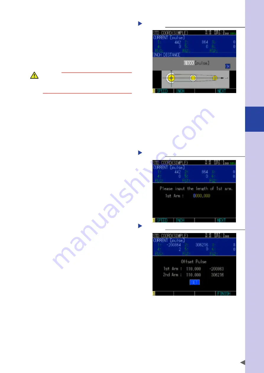
Align the first arm and second arm 

on the line.

Setting the inch amount

Step 2

Move the first arm and second arm using 
the Jog key operation or Jog operation in 
the servo off status to the position where 
they are aligned, and then press the F4 key 
(NEXT). At this time, the direction shown in 
the figure above becomes the +X direction.

WARNING 

When performing the operation with the Jog key, 
the robot is in operation. Therefore, do not enter 
the robot movement range to prevent any hazard.

During the operation with the Jog key, the operation can be performed by adjusting the speed and inch 
distance. 
To adjust the speed, select the F1 key (SPEED) to display the speed setting pop-up screen. Adjust the 
speed on this screen. 
For details about speed adjustment, refer to "2.3 Changing the Jog movement speed" in Chapter 3. 
To adjust the inch amount, select the F2 key (INCH) to display the inch amount adjustment pop-up 
screen. Use 0 to 9 keys to input the pulse value.

*  The first arm and second arm of the robot described in this manual are equivalent to the X-arm and 

Y-arm of the YRC controller.

Step 3

Input the arm lengths.

Inputting the first arm and 

second arm lengths

Step 3

Use 0 to 9 keys to input the first arm length, 
and then press the F4 (NEXT). 
Next, input the second arm length, and then 
press the F4 key (NEXT).

Step 4

Set the standard coordinates.

Check the arm length and offset pulse value. 
Select [SET], and then press the ENTER key to 
save the settings. After the settings have been 
saved, press the F4 key (FINISH) or ESC key to 
exit the setting. 
When pressing the F4 key (FINISH) or ESC key 
in the status that the settings are not saved, 
the setting is completed without saving. 
If the calculation cannot be performed, 
corresponding alarms occur.

Checking the settings

Step 4

Содержание YRCX Series

Страница 1: ...7 6HULHV DW 1R 1 5 5RERW RQWUROOHU 23 5 7 21 0 18 6 5 5RERWV 5 6HULHV...

Страница 2: ......

Страница 3: ...mergency stop 1 3 2 1 Emergency stop release and alarm reset 1 3 3 Power ON procedures 1 5 4 Usage environments 1 6 Chapter 2 System overview 1 Operation overview 2 1 2 The YRCX robot controller 2 2 2...

Страница 4: ...2 2 Changing the display units 3 7 2 3 Changing the Jog movement speed 3 7 2 4 Changing the inch distance 3 8 2 5 Inputting point data by teaching 3 8 2 6 Jumping the point display 3 9 3 Point trace 3...

Страница 5: ...Automatic dual offset setting 3 35 6 1 2 Adjusting dual offset 3 36 Chapter 4 Edit 1 Point editing 4 1 1 1 Inputting editing point data 4 3 1 2 Point data input by teaching 4 4 1 3 Point data input b...

Страница 6: ...s 4 24 4 Hand definitions 4 25 4 1 Data format of hand definition 4 26 4 1 1 SCARA type robots 4 27 4 2 HAND EDIT CREATING NEW HAND screen 4 28 4 3 Creating new hand definitions 4 30 4 4 Editing hand...

Страница 7: ...coordinates by simple teaching 4 70 9 2 Setting the standard coordinate by 3 point teaching 4 72 9 3 Setting the standard coordinate by 4 point teaching 4 73 9 4 Setting the standard coordinate by bot...

Страница 8: ...8 8 2 Setting the clock 5 9 9 Generation 5 10 Chapter 6 Monitor 1 Overview of function 6 1 2 Current position display 6 1 3 I O status display 6 2 3 1 I O monitor list 6 3 3 2 I O monitor detail 6 4 3...

Страница 9: ...larm related to the data input A 21 5 Alarm related to the syntax of the robot language compile A 23 6 Alarm related to the robot language execution A 30 9 Alarm related to the memory A 39 10 Alarm re...

Страница 10: ......

Страница 11: ...nd or related product not approved by OMRON or OMRON sales representative 4 Use of any other than genuine parts and specified grease and lubricant 5 Incorrect or inadequate maintenance and inspection...

Страница 12: ......

Страница 13: ...nformation before reading this manual Introduction i About this manual i Safety precautions ii Signal symbols ii Overview of the YRCX iii Before using the robot controller Be sure to read the followin...

Страница 14: ......

Страница 15: ...e degree of freedom in movement To use OMRON robots and controllers safely and correctly be sure to comply with the safety instructions and precautions described in this manual Failure to take necessa...

Страница 16: ...nd controllers safely and correctly first read the separate volume Safety Instructions and always follow the safety rules and instructions Please note however this manual cannot cover all items regard...

Страница 17: ...high level robot language that conforms to the industrial robot programming language SLIM This robot language allows easy programming even of complex movements such as multi task operations Standard...

Страница 18: ...t cables separate from the robot controller power connection lines and other equipment power lines Using in close contact with lines carrying power may cause malfunctions or abnormal operation TIP Per...

Страница 19: ...ter 1 Using the robot safely 1 Emergency action when a person is caught by robot 1 1 2 Emergency stop 1 3 2 1 Emergency stop release and alarm reset 1 3 3 Power ON procedures 1 5 4 Usage environments...

Страница 20: ......

Страница 21: ...hands WARNING The vertical axis of the vertical use robot will slide down when the brake is released causing a hazardous situation Prop up the vertical axis with a support stand before releasing the...

Страница 22: ...the brake For the vertical axis when the brake is released the vertical axis may drop Therefore check that the vertical axis is supported by the table etc and then release the brake To apply the brak...

Страница 23: ...nterface in the YRCX user s manual for details Programming box Emergency stop button 2 1 Emergency stop release and alarm reset To return to normal operation after emergency stop release the emergency...

Страница 24: ...en Press on the programming box The QUICK MENU screen will appear Use the cursor keys to select Servo Operation and then press Step 3 QUICK MENU screen Step 4 Turn on the motor power and servo Use the...

Страница 25: ...erial I O settings Refer to the YRCX user s manual for details Step 1 Check the setup and connections Make sure that the necessary setup and connections are correctly completed according to the instru...

Страница 26: ...components Vibration and shock Do not apply strong shocks to the controller Do not install the controller in locations subject to large vibrations or shocks The controller may malfunction or break do...

Страница 27: ...4 3 1 Part names and functions 2 4 3 2 Connection to the robot controller 2 5 3 3 Programming box screen 2 5 4 Operation key 2 6 4 1 Operation key layout 2 6 4 2 Basic key operation 2 6 4 3 Function...

Страница 28: ......

Страница 29: ...allel I O is an optional function Used for I O of emergency stop signal enable switch signal etc Used for communication through RS 232C RS 232C interface Used for communication through Ethernet Ethern...

Страница 30: ...isplays the controller status For details refer to 2 2 7 segment LED display function in this Chapter 2 PWR LED Lights up when the power is turned on 3 AC IN Supplies the AC power to the controller 4...

Страница 31: ...n return to origin complete emergency stop released SRV ORG E STOP Servo off return to origin incomplete emergency stop SRV ORG E STOP Servo off return to origin incomplete emergency stop released SRV...

Страница 32: ...ation mode between AUTO and MANUAL To execute the automatic operation AUTO it is necessary to set the manual lock switch at OFF To operate the robot manually during teaching work it is necessary to se...

Страница 33: ...of the programming box is composed of three areas as shown below Example of programming box screen 2 Data area 1 System line 3 Guide line 1 System line top line The current hierarchy is displayed on t...

Страница 34: ...are 3 types of keys function keys control keys and data keys LED displays show selected key types Operation key layout 4 Key type display LED 1 Function keys 3 Data keys 2 Control keys 4 2 Basic key...

Страница 35: ...ssed the data changes like A B C 2 Every time the input key is pressed the data changes like to 4 3 Function keys To operate the programming box select the submenus by pressing the function keys If th...

Страница 36: ...rolls one screen right when the scroll function is on 3 Edit keys Toggles between Insert and Overwrite modes The cursor appears in Overwrite mode and appears in Insert mode Deletes one character left...

Страница 37: ...ompletes the data input on the cursor line When the item is selected on the screen pressing this key will make the setting 5 Hierarchy structure The hierarchy structure is shown below Basic hierarchie...

Страница 38: ...When pressing the QUICK MENU screen will appear The QUICK MENU screen is shown below Use the cursor keys to select a menu and then press the ENTER key The screen for the selected menu will appear 1 Co...

Страница 39: ...peration Edit Point Edit WARNING Program Edit Shift Coordinate Hand Definition Pallet Definition Parameter Area Check Output Standard Coordinate GEP Setting Calibration System History WARNING Check Pr...

Страница 40: ...state Current Monitor Current Position Gripper State Tracking Monitor NOTE Each notation in the tables means The operation can be performed The function is partly limited The operation cannot be perf...

Страница 41: ...the robot number to select and press the ENTER key Press the F1 key ARM TYPE to change the hand system ROBOT CHANGE screen 6 Shift Coordinate Sets the shift coordinates For details refer to 3 Shift co...

Страница 42: ...ect a hierarchy and press the ENTER key Relevant hierarchy menu will appear For example when selecting Edit on the initial screen the Edit menu will appear To move to the lower hierarchy select the me...

Страница 43: ...F5 JOG F6 EDIT F7 JUMP F8 AXIS F9 GRIPPER Point Trace Automatic Operation F1 SPEED F2 STOP F3 ALL TASK F4 JUMP F5 PROGRAM F6 DEBUG F7 REGISTER F8 RELEASE F9 PRIORITY F10 RESET F11 ALL RESET1 F12 RESTA...

Страница 44: ...F4 PASTE F5 FIND F6 JUMP F7 CHECK F1 NEW F2 EDIT F3 SEQ CMP F4 MAIN F5 AUTO OPE F6 ATRIB F7 DEL F8 RENAME F9 COPY Program Edit F4 NEXT F1 NEW F1 SPEED F2 INCH F4 NEXT F1 SPEED F2 INCH F4 NEXT F1 SPEED...

Страница 45: ...3 4POINT F1 SPEED F2 INCH F4 NEXT F1 SPEED F2 INCH F4 NEXT F1 SPEED F2 INCH F4 NEXT F1 SPEED F2 INCH F4 NEXT F1 NEW F1 EDIT F1 SPEED F2 INCH F4 NEXT F1 SPEED F2 INCH F4 NEXT F1 SPEED F2 INCH F4 NEXT C...

Страница 46: ...F2 DRIVER F3 RBT AXIS F4 AXIS ATRB F5 GRIPPER F1 UNIT F1 Ethernet F2 ONLINE F3 OFFLINE F4 INIT Monitor IO Task Driving State Current Monitor Current Position Gripper Status Tracking Monitor F1 SAVE F...

Страница 47: ...7 2 4 Changing the inch distance 3 8 2 5 Inputting point data by teaching 3 8 2 6 Jumping the point display 3 9 3 Point trace 3 9 3 1 PTP motion 3 10 3 2 Linear interpolation motion 3 11 3 3 Arch moti...

Страница 48: ...3 24 4 11 3 Executing the next step 3 24 4 11 4 Break points 3 24 4 11 5 RUNTO 3 25 5 Origin return 3 26 5 1 Return to origin operation 3 27 5 2 Return to origin procedure 3 29 5 3 Absolute reset mar...

Страница 49: ...operation is performed to temporarily turn on or off the servo so as to perform the direct teaching WARNING When the brake is provided selecting FREE will release the brake However when releasing the...

Страница 50: ...n be set in robot units or axis units on the SERVO OPERATION SEP screen Step 1 Display the SERVO OPERATION SEP screen SERVO OPERATION SEP screen Confirming the servo free change Step 4 Press the QUICK...

Страница 51: ...isplayed when the setting is GET or the operation is in MANUAL mode SEQ Displayed when the sequence program is executed When using multiple robots the robot number display is changed by changing the t...

Страница 52: ...robot starts to move when a Jog key is pressed To avoid danger do not enter the robot movement range NOTE When using multiple robots check the name of the robot to be operated and then perform the Jog...

Страница 53: ...334 Over soft limit appears and the robot does not move 2 When the current position is displayed in mm units mm is displayed on the right of CURRENT on the programming box screen When the tool coordi...

Страница 54: ...mm units is 5mm If robot movement beyond the soft limits is attempted with the Jog keys the error message 2 334 Over soft limit appears and the robot does not move If robot movement beyond the shift...

Страница 55: ...m units Cartesian coordinates tool coordinates 1 Displays the current position with a number consisting of an integer and a decimal fraction 1 This is used only when the hand data fixed to the R axis...

Страница 56: ...int data by teaching The current position of the robot can be obtained as point data by teaching WARNING The robot moves during teaching To avoid danger do not enter the robot movement range CAUTION W...

Страница 57: ...F7 key JUMP on the JOG screen The point number entry screen will appear Inputting the point number Step 2 Input the point number Input a numeric value and press the ENTER key Step 3 Set the value you...

Страница 58: ...axes point trace Step 1 Display the PTP ALL screen To display the screen select Operation from the initial screen and then Point Trace or press the F2 key PTP on the LINEAR or ARCH screen PTP ALL scre...

Страница 59: ...ype Step 4 Execute point trace Press the RUN key and the robot moves by PTP motion to the position of the selected point The trace speed is 1 10 of the AUTO movement speed To stop point trace press th...

Страница 60: ...s point trace Step 1 Display the LINEAR SEP screen Press the F3 key LINEAR on the PTP ALL screen Operation Point Trace and then press the F8 key EACH LINEAR SEP screen Step 2 Step 2 Select the point n...

Страница 61: ...er to perform arch motion POS Sets the arch movement position Dist 1 Sets the arch position 1 Dist 2 Sets the arch position 2 Dist 1 arch position 1 and Dist 2 arch position 2 are arch options WARNING...

Страница 62: ...he STOP key For details about how to set the speed refer to 3 4 Setting the speed in this Chapter 3 4 Setting the speed The trace speed is changed on the point trace screen The speed setting procedure...

Страница 63: ...ration Operations related to the robot language program execution are performed during automatic operation The automatic operation provides the AUTO OPE SEP screen where only one task is displayed and...

Страница 64: ...on status WAIT Wait status SUSPENDED Forced suspended status NON EX Unregistered status For details about each task status refer to the YRCX programming manual 6 Program name Displays the selected pro...

Страница 65: ...he initial screen and then press the ENTER key Next select Automatic Operation and then press the ENTER key The AUTO OPE SEP screen will appear AUTO OPE SEP screen Step 1 Step 2 Select the program Use...

Страница 66: ...xecution If turned off the internal system data may be corrupted and the program may not restart when the power is again turned on Always be sure to terminate or stop the program before turning the po...

Страница 67: ...et it is selected automatically Current program The program that is executed last in the task 1 or the program that is assigned last to the task 1 is selected 4 4 Registering and releasing task The pr...

Страница 68: ...UTO OPE screen Press the F3 key ALL TASK on the AUTO OPE SEP screen The AUTO OPE ALL TASK screen will appear AUTO OPE ALL TASK screen When pressing the F3 key SEP the AUTO OPE SEP screen will appear 4...

Страница 69: ...e the cursor keys to select STOP and then press the ENTER key Sequence program run stop confirmation screen 4 9 Restarting the program The program in the SUSPENDED status is restarted To restart the p...

Страница 70: ...splayed when the setting is GET or the operation is in MANUAL mode SEQ Displayed when the sequence program is executed When using multiple robots the robot number display is changed by changing the ta...

Страница 71: ...ne 1 Hierarchy Displays the current hierarchy 2 Robot setting status Displays the currently selected robot shift and so on Specified shift coordinate number Specified hand definition number Specified...

Страница 72: ...ution line display and move the execution line display to the next line When the command is a sub routine or sub procedure its first line is executed 4 11 2 Skipping a step When pressing the F3 key SK...

Страница 73: ...eration Debug Step 2 Cancel the break point When pressing the F7 key BP DEL the break point of the selected line is canceled and shown on the right of the line number disappears To cancel all the set...

Страница 74: ...h on each axis Axis parameter Origin speed Sets the speed at which to perform return to origin or absolute search Origin shift Sets the offset of origin position data Origin method Sets the method for...

Страница 75: ...n procedure for instructions on how to perform return to origin 1 Return to origin operation using the sensor method 1 3 2 Return to origin start position Origin sensor Return to origin direction 1 Be...

Страница 76: ...method return to origin can start from any position 2 Upon starting return to origin the robot starts moving in the return to origin direction 3 When the robot axis strikes and detects the stroke end...

Страница 77: ...p 1 Move to the ORIGIN RTN TRQ SENS screen Use the cursor keys to select Operation from the initial screen and then press the ENTER key Next use the cursor keys to select Origin Return and then press...

Страница 78: ...eturn to origin needs to be performed again when turning off the controller 5 3 Absolute reset mark method procedure For axes with mark method the return to origin is not performed For the mark method...

Страница 79: ...nitial screen The ORIGIN RTN TRQ SENS screen will appear Press the F1 key MARK on it ORIGIN RTN MARK screen Step 1 Step 2 Select the axis to perform absolute reset Use the cursor keys to select the ax...

Страница 80: ...n and then press the ENTER key ORIGIN RTN MARK screen Step 1 Step 2 Move the axis to a position where absolute reset is possible Press the emergency stop button on the programming box to put the robot...

Страница 81: ...chine reference is within the tolerable value and that the status is OK Press the ESC key to return to the initial screen ORIGIN RTN MARK screen Step 5 5 4 Return to origin for all robots Step 1 Move...

Страница 82: ...sub axis origin position Origin complete position Main axis Sub axis Origin position range without setting dual offset Origin positions are different The range colored in light blue Dual offset adjust...

Страница 83: ...t and display the execution pop up screen Execution pop up screen Step 4 Step 5 Input 2 to set Mode and press the ENTER key Changing the setting Step 5 Step 6 Press the RUN key to perform dual return...

Страница 84: ...pulse The origin position is offset by 200 pulse to direction Make dual offset the minus direction direction Main axis Origin position by automatic setting DualOfst 1000 pulse DualOfst 1200 pulse The...

Страница 85: ...tween the insert and overwrite modes 4 11 2 3 4 Inserting a line 4 12 2 3 5 Deleting one character 4 12 2 3 6 Backspace 4 12 2 3 7 Copying cutting a program 4 12 2 3 8 Searching a character string 4 1...

Страница 86: ...Setting point of pallet definitions 4 41 7 Parameters 4 42 7 1 Parameter setting conditions 4 42 7 2 Setting the parameters 4 42 7 3 Parameter list 4 44 7 4 Parameter descriptions 4 47 7 4 1 Controll...

Страница 87: ...tem flag or when no numeric value is specified the hand system flag setting becomes none 0 When a numeric value other than 0 1 and 1 is specified for the first arm rotation information and second arm...

Страница 88: ...g the target robot on the QUICK MENU 3 Current position Displays the current position of the robot The current position is displayed by an integer when using pulse units When using mm units the positi...

Страница 89: ...the jump destination point number COPY Copies the point data DEL Deletes the point data UNIT Changes the display unit of the current position to pulse mm and mm tool in order TRACE Moves to the PTP AL...

Страница 90: ...x 1 after converted from mm to pulse is 540 00 degrees x 180 00 degrees 1 This angle data is that the pulse data after converted into the joint coordinates is converted into the angle from the mechan...

Страница 91: ...input For details about jump function refer to 1 4 Jumping point display in this Chapter POINT EDIT screen Step 1 Step 2 Display the JOG screen Press the F6 key JOG to display the JOG screen JOG scree...

Страница 92: ...operation in Chapter 3 or the YRCX user s manual 1 4 Jumping point display Point data can be displayed from the point numbers you have specified When pressing the F1 key JUMP on the POINT EDIT screen...

Страница 93: ...ting point trace Positions of point data you have input can be checked by actually moving the robot To execute the point trace press the F5 key TRACE on the POINT EDIT screen Edit Point Edit to displa...

Страница 94: ...t and so on Specified shift coordinate number Specified hand definition number Specified robot number Specified speed ALM Displayed when any alarm occurs SRV Displayed when the servo is on AUTO Displa...

Страница 95: ...n NOTE Refer to the separate YRCX programming manual for details on the programming language For details automatic operation refer to 4 Automatic operation in Chapter 3 2 1 Selecting the program The P...

Страница 96: ...r Press the ESC key to cancel the new program creation and return to the previous screen Be aware that the existing program is overwritten when registering the same program name as that already regist...

Страница 97: ...KB Since the program area is shared with the point data the capacity may decrease depends on the amount of point data Example When the amount of point data is 10000 the capacity decrease 600 KB and a...

Страница 98: ...or cut range Press the F1 key RANGE and specify the copy or cut range with the cursor keys Pressing the up down cursor key will cancel the range designation NOTE A range including multiple lines canno...

Страница 99: ...Edit Program Edit Edit to display the pop up screen Step 2 Input the step number Input the step number and then press the ENTER key The program is displayed from the specified step 2 3 10 Checking ent...

Страница 100: ...the pop up screen Setting for the main program Step 2 Step 2 Set the program for the main program Select OK and press the ENTER key The selected program is set for the main program and m is shown in...

Страница 101: ...y the delete confirmation pop up screen Select OK and press the ENTER key to delete the program Select CANCEL or press the ESC key to return to the previous screen NOTE When the attribute of the progr...

Страница 102: ...key to copy the program To return to the previous screen without changing select CANCEL or press the ESC key NOTE Valid program numbers are between 1 and 100 Characters 0 to 9 A to Z and _ underscore...

Страница 103: ...s Sn 1 dX mm 2 dY mm 3 dZ mm 4 dR degree n 0 to 39 NOTE n corresponds to the shift coordinate number Up to 40 shift coordinates can be set Example S1 Shows the shift coordinate S1 When the shift amoun...

Страница 104: ...shown below will appear SHIFT COORDINATE screen 6 Shift coordinates 7 Shift coordinate range 2 Robot setting status 8 Guide line 1 Hierarchy Press the F1 key EDIT to show the screen below SHIFT EDIT s...

Страница 105: ...point 4 Coordinate unit system Displays the coordinate unit system The unit shows pulse or mm 5 Shift number Displays the shift number selected on the SHIFT EDIT screen 6 Shift coordinates Displays t...

Страница 106: ...HIFT EDIT screen Step 3 Press the F2 key NEW NOTE The values input before pressing the F1 key NEW will be cleared Creating new shift coordinates Step 2 5 Step 4 Input the shift coordinates Use the cur...

Страница 107: ...the F1 key EDIT to display the SHIFT EDIT screen Step 3 Input the shift coordinates For details on how to input values refer to Step 4 through Step 6 of 3 1 Creating new shift coordinates in this Chap...

Страница 108: ...ss the F4 key NEXT to decide the position NOTE Determine the points to teach accurately otherwise the shift coordinates cannot be set correctly Setting inch distance Step 3 Press the F1 key SPEED to d...

Страница 109: ...he coordinate direction after teaching two points The Z axis value of point 1 is that of the shift coordinate WARNING The robot moves during teaching To avoid danger do not enter the robot movement ra...

Страница 110: ...hat of point 2 will not be reflected to the shift coordinates Step 6 Set the shift coordinate Checking the setting Step 6 Check the shift coordinate to be displayed Select SET and press the ENTER key...

Страница 111: ...definitions However when using SCARA type robots the standard coordinates need to be set For details about how to set the standard coordinates refer to 8 Standard coordinates in this Chapter NOTE Whe...

Страница 112: ...definition you want to use has any input data this means that the hand is already defined 5 Guide line Displays the contents assigned to the function keys 4 1 Data format of hand definition Hn Robot...

Страница 113: ...or R Hands attached to 2nd arm SCARA type 1 5 0 0 0 m m 20 00mm HAND 1 HAND 0 S t a n d a r d 2 n d a r m 5000 pulse Input example H0 H1 ROBOT 1 Robot number ROBOT 1 Robot number 1 0 Pulse 1 5000 Puls...

Страница 114: ...nd definition scrolls up or down to display the set contents of this shift number by three when the scroll function is ON EDIT Edits the hand data currently selected SELECT Selects the hand definition...

Страница 115: ...Hand number Displays the hand number selected on the HAND EDIT screen The selected hand number is highlighted 6 Hand data Displays the hand data of the hand number selected on the HAND EDIT screen Whe...

Страница 116: ...scroll function is ON Selecting the hand definition number Step 1 Step 2 Press the F1 key EDIT to display the HAND EDIT screen Step 3 Press the F2 key NEW NOTE The values input before pressing the F1...

Страница 117: ...display the HAND EDIT screen Step 3 Press the F2 key NEW Refer to Step 4 through Step 6 of 4 1 Creating new hand definitions in this Chapter for details on how to input values NOTE All the values inpu...

Страница 118: ...ends before saving 4 6 Selecting hand definitions To use the hand definition select the hand definition you have created NOTE The hand definition cannot be edited only when creating or editing hand de...

Страница 119: ...work definition number RB1 Specified robot number SP30 Specified speed ALM Displayed when any alarm occurs SRV Displayed when the servo is on AUTO Displayed when the control setting is RELEASE This i...

Страница 120: ...or counterclockwise value degree Setting all work definition values to 0 means that no work definition is set Robot Movement The robot moves the tip of the work n to the specified point The direction...

Страница 121: ...a value Step 5 Set the values you have input After inputting the values press the ENTER key to set them Press the ESC key to cancel the data you have input and return to the previous screen Step 6 Re...

Страница 122: ...y for the cursor line before the data entry is completed 5 4 Selecting work definitions To use the work definition select the work definition you have created NOTE The work definition cannot be edited...

Страница 123: ...be defined as the positions on one pallet is 32767 Data in the point data area is used point data on the for pallet definitions NOTE When using multiple robots the pallet definitions are used commonl...

Страница 124: ...ion is in MANUAL mode SEQ Displayed when the sequence program is executed When using multiple robots the robot number display is changed by changing the target robot on the QUICK MENU 3 Current positi...

Страница 125: ...g it newly Set the pallet definition after creating it newly Step 1 Select the pallet definition number with the cursor keys The pallet definition number scrolls up or down to display the set contents...

Страница 126: ...e the cursor position Deletes one character at the cursor position Returns to the previous screen Step 1 Select the pallet definition number with the cursor keys The pallet definition number scrolls u...

Страница 127: ...nge to avoid danger Step 6 Teach other points Teaching other points Step 6 Teach P 2 P 3 P 4 and P 5 only when specifying 3D in the same way as teaching P 1 Step 7 Specify the pallet definition Check...

Страница 128: ...rectly this may cause alarm or malfunction So be sure to set the parameters correctly Save the data files program point point comment parameter shift hand and pallet etc saved inside the YRCX to an ex...

Страница 129: ...en PARAMETER AXIS screen PARAMETER DRIVER screen PARAMETER IO screen PARAMETER OPTION screen The screen setting depends on the robots and options to use NOTE Changing the driver parameters might influ...

Страница 130: ...oint stop mode BRKSTPMD 0 HOLD 1 HALDALL 1 Shift on area check out SFTONACO 0 INVALID 1 VALID 1 1 Contact your distributor for changing these parameters as editing them may influence the robot control...

Страница 131: ...ficient ACCEL 1 to 100 100 Decel rate DECRAT 1 to 100 100 Tolerance TOLE 1 to value depending on the model 80 pulse OUT position OUTPOS 1 to 9999999 2000 pulse CONT pulse CONTPLS 0 to 9999999 0 pulse...

Страница 132: ...ters For details about parameters refer to 10 8 Option board related parameters in this Chapter Name Identifier Setting range Initial value Separate manual Option board enable OPTENBL 0 INVALID 1 VALI...

Страница 133: ...position before executing again does not change When executing return to origin or absolute reset the target position after the relative motion stop is reset 1 RESET The relative motion is newly perfo...

Страница 134: ...program reset when it starts When this parameter is initialized 0 INVALID is set Setting Meaning 0 INVALID The program reset is not performed 1 VALID The program reset is performed Permission to rese...

Страница 135: ...atus Break point stop mode BRKSTPMD This parameter sets whether the break point stops only the relevant program or all the programs When this parameter is initialized 1 HOLD ALL is set Setting Meaning...

Страница 136: ...llary axis When different position detection methods absolute specifications or incremental specifications are mixed in one robot the order of return to origin operations may vary depending on the ret...

Страница 137: ...set When moving on the Cartesian coordinates in the SCARA robot or when performing coordinate conversion pulse coordinates Cartesian coordinates the hand system setting becomes important Setting Mean...

Страница 138: ...er numeric value including a period the unit is automatically converted into the pulse value Acceleration coefficient ACCEL This parameter sets the acceleration deceleration during robot movement in a...

Страница 139: ...lized the value unique to the model is set NOTE Input the OUT valid position with the 0 to 9 keys key and key When the value input with the keys is a real number numeric value including a period the u...

Страница 140: ...o that the remaining distance becomes arch pulse 2 when the movement of other axes is completed 3 shown in the figure above 4 When all axes enter the OUT valid position range the command is completed...

Страница 141: ...become long Take great care when using the robot with the acceleration coefficient decreased extremely NOTE When the tip swings during acceleration of the manual movement decrease this value to suppr...

Страница 142: ...ot When this parameter is initialized the value unique to the model is set 0 Mark method Method to set the origin position such as match mark by the user 1 Sensor method Origin position detection meth...

Страница 143: ...rn incomplete status Arm length ARMLEN For SCARA type robots this parameter sets the X and Y arm lengths When this parameter is initialized the unique value to the model is set Additionally this param...

Страница 144: ...ts no error 1 to 0277 Octal Outputs an error from the port specified by DO or SO The general purpose output used in error output is OFF in any case of follows 1 Servo was turned on 2 Program reset was...

Страница 145: ...annot be used 1 VALID Remote command can be used DI17 mode DI17MD This parameter sets the operation of the dedicated input DI17 SI17 When this parameter is initialized 0 ABS is set Setting Meaning 0 A...

Страница 146: ...fter turning off and on the power Real time output RTOENBL This parameter sets the real time output function enabled or disabled When this parameter is enabled items registered in the real time output...

Страница 147: ...his parameter sets the gripper servo status when the emergency stop button is pressed When this parameter is initialized 1 ON is set Setting Meaning 0 OFF The remote command cannot be used 1 ON The gr...

Страница 148: ...is performed after all the robots return to origin 1 BEFORE Return to origin of the gripper is performed before all the robots return to origin DeviceNet address ID DEVADD This parameter sets the Devi...

Страница 149: ...address subnet mask and gateway is 0 0 0 0 SIOW extension SIOWEXT This parameter sets the SIOW extension enabled or disabled When this parameter is enabled the word IO area in the field network is ex...

Страница 150: ...o not set this to VALID except the case that it is necessary to load the parameters from later version controller into the earlier one NOTE New parameters may added as the controller software upgradin...

Страница 151: ...ent in the unit system and the area check output cannot be performed If it is in such a state during automatic operation the operation will be stopped and an error occurs The area check output where a...

Страница 152: ...arameter Refer to 7 2 Initializing area check output in this Chapter Editing the area check output Step 2 Step 2 Edit or create area check output Select the setting value to edit with the cursor keys...

Страница 153: ...20 to 277 1 DO 20 to 277 2 SO 20 to 277 3 MO 0 to 277 NOTE The output state may change unexpectedly when the output ports overlap used in the program and area check output Therefore make sure to set...

Страница 154: ...arm tip in the direction of the Cartesian coordinates Using PALLET definitions SHIFT coordinates and HAND definitions Using commands requiring coordinate conversion such as linear circular interpolati...

Страница 155: ...arm rotation centers M2 Second arm length distance between the second arm and R axis rotation centers 2 Offset pulse M1 X axis offset pulse angle formed by the first arm when the axis 1 motor is locat...

Страница 156: ...Moves to the screen that allows you to set the standard coordinates by 4 point teaching BOTH HND Moves to the screen that allows you to set the standard coordinates by both handed system teaching Ret...

Страница 157: ...g the Jog movement speed in Chapter 3 To adjust the inch amount select the F2 key INCH to display the inch amount adjustment pop up screen Use 0 to 9 keys to input the pulse value The first arm and se...

Страница 158: ...XT to set the position Setting the inch distance Step 2 WARNING When performing the operation with the Jog key the robot operates Therefore do not enter the robot movement range to prevent any hazard...

Страница 159: ...and offset pulse value Select SET and then press the ENTER key to save the settings After the settings have been saved press the F4 key FINISH or ESC key to exit the setting When pressing the F4 key F...

Страница 160: ...og movement speed in Chapter 3 To adjust the inch amount select the F2 key INCH to display the inch amount adjustment pop up screen Use 0 to 9 keys to input the pulse value Step 3 Determine the points...

Страница 161: ...handed onthe STD COORD screen EditStandard Coordinate Step 2 Confirm change the arm length Step 2 Confirm change the arm length The value firstly shown in the entering form is the default value of th...

Страница 162: ...P1 and P2 so that they are parallel to the X or Y axis in the new standard coordinates Step 6 Determine the direction from P1 to P2 Determine the direction from P1 to P2 Step 6 Using the F1 key X to t...

Страница 163: ...se both of the left and right handed system if each point is set in the same handed system an incorrect value will be estimated TIP how to optimize the precision Concerning the teaching of P1 the more...

Страница 164: ......

Страница 165: ...2 4 2 Option information 5 3 4 3 Clock 5 3 4 4 Version 5 3 4 5 Configuration 5 4 5 USB memory operation 5 4 5 1 Saving the data 5 4 5 2 Loading the data 5 5 6 Execution level 5 6 6 1 Changing access l...

Страница 166: ......

Страница 167: ...ting System History from the initial screen the HISTORY screen will appear The HISTORY screen displays five past alarm history records from the latest Up to 500 records are saved HISTORY screen The al...

Страница 168: ...System Property from the initial screen the property screen will appear The property screen displays the robot information option information clock and version 4 1 Robot information The robot names c...

Страница 169: ...plays that the option DIO with the PNP specifications is installed S Standard DIO 1 to 4 Expanded DIO2 D_Net DeviceNet unit ENet_IP EtherNet IP unit Profi_B PROFIBUS unit Profi_N PROFINET unit YCLnkE_...

Страница 170: ...aded to the controller Select System USB Memory from the initial screen to display the USB MEMORY screen USB MEMORY screen NOTE It is recommended to save the internal data when robot controller settin...

Страница 171: ...equired to the data to have been saved into the OMRON folder immediately beneath the USB memory Step 1 Select System USB Memory LOAD from the initial screen Use the cursor keys to select the type of t...

Страница 172: ...initial screen and then press the ENTER key Next select Execution Level and then press the ENTER key The ACCESS LEVEL screen will appear Step 2 Input the access level to set Input the access level an...

Страница 173: ...limited to its 3 3 Exclusive IO VALID INVALID Sets the dedicated input of the I O interface VALID or INVALID Even when set INVALID the general purpose inputs and outputs can be used 4 RS 232C VALID IN...

Страница 174: ...name data SFT Deletes the shift coordinate data HND Deletes the hand definition data PRM Initializes the parameter data PLT Deletes the pallet definition data ION Deletes the I O name data LOG Delete...

Страница 175: ...to execute the initialization process Select the CANCEL button and then press the ENTER key to cancel the initialization process 8 2 Setting the clock The controller is equipped with the clock functi...

Страница 176: ...r axis to be connected to the controller is changed the system generation setting is needed For details about how to operate the system generation contact your distributor CAUTION If the system genera...

Страница 177: ...or 1 Overview of function 6 1 2 Current position display 6 1 3 I O status display 6 2 3 1 I O monitor list 6 3 3 2 I O monitor detail 6 4 3 3 Changing output status 6 4 4 Task driving state 6 5 5 Curr...

Страница 178: ......

Страница 179: ...n information 1 Current position 3 Hand system 1 Current position Displays the current position of the robot The current position in pulse units is displayed by an integer The current position in mm u...

Страница 180: ...displayed NOTE Input and output ports that do not exist as hardware are also displayed I O status display examples are shown below Example of bit I O list display Example of bit I O detail display Exa...

Страница 181: ...the monitor hierarchy select IO and then press the ENTER key The I O monitor list will appear The I O monitor list provides the input status list and output status list The input status list is displ...

Страница 182: ...reen display is updated at constant intervals Press the ESC key to exit the monitor display and return to the initial screen 3 3 Changing output status ON OFF of the DO MO LO TO or SO output can be ch...

Страница 183: ...hen no alarm occurs SRV Servo on status This is not displayed when the servo is off AUTO Control setting is set RELEASE This is not displayed when the control setting is GET and the operation is in th...

Страница 184: ...e Displays the contents assigned to the function keys 10 Message Displays the output of PRINT command in the program 5 Current monitor The current torque to each axis rated torque of the selected robo...

Страница 185: ...e data input A 21 5 Alarm related to the syntax of the robot language compile A 23 6 Alarm related to the robot language execution A 30 9 Alarm related to the memory A 39 10 Alarm related to the envir...

Страница 186: ......

Страница 187: ...location during program operation Current status is Programming box screen status example Nothing is displayed on screen Error message appears on screen Robot servo status example Servo won t turn on...

Страница 188: ...set Step 2 Check the alarm status Send the command READ SCK from the personal computer The alarm code is received when an alarm occurs No alarm code is received when any alarm does not occur 2 2 Chec...

Страница 189: ...is inserted Replace the programming box and check operation Plug in the PB connector correctly Replace the programming box Replace the controller 3 Although the controller turns on the alarm number i...

Страница 190: ...tion in program language Set a correct tip weight parameter Set a correct acceleration parameter Make a correct setting in the program language A mechanical problem occurred Check for resonance in the...

Страница 191: ...24 V DC A problem in signal connection occurred Check the I O interface connector wiring Correct the I O interface connector wiring An alarm occurred Connect the programming box and check the alarm by...

Страница 192: ...of the controller alternately displays alarm group number and alarm classification number The alarm code consists of two elements group and classification Each code is classified as follows XX YYY Gr...

Страница 193: ...of the robot language compile 6 Alarm related to the robot language execution 7 Not used 8 Not used 9 Alarm related to the memory 10 Alarm related to the environment and general hardware 11 Not used...

Страница 194: ...99 Internal error Operation stop Fan error 800 to 899 Servo brake Overload 900 to 999 Immediate servo off Restart system Over current Driver communication failure 3 Alarm occurrence location list T Ta...

Страница 195: ...m history can be checked from the programming box Information on the alarm occurrence location axis option unit and so on may be added 0 Operation messages 0 0 OK Code H0000 H0000 Meaning Cause Correc...

Страница 196: ...tting to VALID 0 23 No right of PRINT INPUT Code H0000 H0017 Meaning Cause The PRINT INPUT statement was executed without setting Action Change the setting of PRINT INPUT using channel of the controll...

Страница 197: ...mmand execution was stopped by external stop command Action 1 9 Arrived at debug Code H0001 H0009 Meaning Cause The program in execution reached the break point and stopped The program executed by the...

Страница 198: ...ting position is out of the movement range Action a Set the standard coordinates correctly b Change the operating position within the movement range 2 303 Shift cal failed Code H0002 H012F Meaning Cau...

Страница 199: ...ode H0002 H0135 Meaning Cause Y axis exceeded the shift coordinate range Action Change the operation position to the inside of the shift coordinate range Change the shift coordinate range 2 310 Z exce...

Страница 200: ...ation speed exceeded the specified level Action Change the specified speed 2 327 Circular arc cal failed Code H0002 H0147 Meaning Cause The circular interpolation operation point is incorrect Action S...

Страница 201: ...ange the soft limit value 2 335 Over movable range Code H0002 H014F Meaning Cause There is a point outside the movement range on the movement path Action Specify the movement path to be within the mov...

Страница 202: ...hand definition of Y axis attachment Quit to use the hand definition 2 343 Illegal axes R selected hand Code H0002 H0157 Meaning Cause a Tool coordinate jog operation was executed for the auxiliary a...

Страница 203: ...nuous Path motion of SCARA robot has been executed within the prohibited range of the outer CP motion Action The CP motion cannot be executed within the range Move the robot to outside of the range wi...

Страница 204: ...input range Action Set the axis weight within the input range 2 708 System error Tracking Code H0002 H02C4 Meaning Cause Error occurred in software Action Contact your distributor 2 709 System error W...

Страница 205: ...e carrier parameter is the same setting for each carrier 2 714 W carrier can t excute CTMOVE Code H0002 H02CA Meaning Cause CTMOVE cannot be executed while Double carrier collision prevention function...

Страница 206: ...point was not found during search Action Set break points if necessary 3 208 Current program doesn t exist Code H0003 H00D0 Meaning Cause As the current program does not exit Reset can not be executed...

Страница 207: ...ng Cause The sequence program to revise or delete is running Action Stop the sequence program 4 Alarm related to the data input 4 201 Point number error Code H0004 H00C9 Meaning Cause A point number e...

Страница 208: ...w point name 4 210 Illegal point name Code H0004 H00D2 Meaning Cause The specified point name is incorrect Action Input a point name that can be used Save a new point name 4 211 Illegal I O port Code...

Страница 209: ...ssion value 5 204 Bit number error Code H0005 H00CC Meaning Cause The specified bit number is not within 0 to 7 Action Specify a correct bit number 5 206 Digit number error Code H0005 H00CE Meaning Ca...

Страница 210: ...responding FOR statement Action Use the corresponding variable names 5 216 WEND without WHILE Code H0005 H00D8 Meaning Cause There is no WHILE statement corresponding to the WEND statement Action Dele...

Страница 211: ...Add ENDIF statement corresponding to the ELSE statement 5 224 END SUB without SUB Code H0005 H00E0 Meaning Cause a There is no SUB statement corresponding to the END SUB statement b END SUB command w...

Страница 212: ...Meaning Cause An undefined label was used Action Define the undefined label 5 232 Undefined user function Code H0005 H00E8 Meaning Cause Undefined function was called Action Define the undefined funct...

Страница 213: ...the procedure between SUB to END SUB statements Action Delete the target command 5 241 Illegal command outside procedure Code H0005 H00F1 Meaning Cause The command cannot be executed outside the proc...

Страница 214: ...SELECT statement corresponding to the CASE statement 5 248 END SELECT without SELECT Code H0005 H00F8 Meaning Cause There is no SELECT statement corresponding to the END SELECT statement Action Delet...

Страница 215: ...orrespond to that of declared array Change the number of the subscript specified by the array declaration Check if there is an array with the same name and different subscript in other program 5 300 I...

Страница 216: ...ate type error Code H0006 H00CD Meaning Cause a Arithmetic operations of joint coordinate point data and Cartesian coordinate point data were attempted b Joint coordinate system exists in the MOVE C c...

Страница 217: ...tion of START command 6 213 RESTART without SUSPEND Code H0006 H00D5 Meaning Cause The RESTART command was executed for a task not executed by the SUSPEND command Action Confirm the execution of SUSPE...

Страница 218: ...commands were executed in parallel the command cannot be executed because of insufficient memory Action The maximum number of OUT commands that can be run in parallel is 16 6 226 PATH without SET Cod...

Страница 219: ...ause Return to origin was performed by ORIGIN statement or dedicated input while the return to origin method for incremental type axes or semi absolute type axes are set to Mark Action Change the retu...

Страница 220: ...e declared in ON ERROR GOTO b Contact your distributor 6 252 Data out of range Code H0006 H00FC Meaning Cause The specified value is out of the input range Action Specify the value within the input ra...

Страница 221: ...ddition characters exceeds 255 Action a Define the number of character constants within 255 b Set the number of additional characters within 255 6 261 Task stopped Code H0006 H0105 Meaning Cause The t...

Страница 222: ...Code H0006 H010E Meaning Cause The position that cannot be calculated is taught during wizard Action Teach again at the correct position 6 271 Can t be in hand use Code H0006 H010F Meaning Cause The...

Страница 223: ...an coordinate movement The robot puts into the origin incomplete status by the following reasons The absolute batteries were removed from the controller or retained position became unstable by absolut...

Страница 224: ...turn to origin cannot be performed b Set the R axis stack correctly c Set both Z and R axis return to origin methods to the ZR stroke end method d Set Z and R axis one each for the ZR stroke end metho...

Страница 225: ...Error occurred in software Action Contact your distributor 9 Alarm related to the memory 9 300 Memory full Code H0009 H012C Meaning Cause There is no available space in the program or point data area...

Страница 226: ...ift data 9 707 Hand data destroyed Code H0009 H02C3 Meaning Cause Part or all of the hand data has been destroyed Action Initialize the hand data 9 709 Pallet data destroyed Code H0009 H02C5 Meaning C...

Страница 227: ...een destroyed Action Initialize the controller 9 717 Program register data destroyed Code H0009 H02CD Meaning Cause Part or all of the program register has been destroyed Action Initialize the program...

Страница 228: ...rt or all of the out status data has been destroyed Action Reset the output port 9 729 Sequence object destroyed Code H0009 H02D9 Meaning Cause Part or all of the sequence object program has been dest...

Страница 229: ...ode H0009 H0385 Meaning Cause The robot type or axis number designation in the system generation data is incorrect Action Back up the current data then send load the data that is proper for the target...

Страница 230: ...r to VALID 10 219 Illegal axis type Code H000A H00DB Meaning Cause This axis type cannot be set Action Check the axis setting Back up the current data then send load the data that is proper for the ta...

Страница 231: ...real time clock 10 900 Turn on power again Code H000A H0384 Meaning Cause System generation was performed because of changing robot and so on Parameters were changed through the communication System g...

Страница 232: ...ting the CADDQUEV command Action Execute the CTVISION command on the tasks or counters beforehand 12 203 Tracking calibration incomplete Code H000C H00CB Meaning Cause Tracking function was executed w...

Страница 233: ...Code H000C H012D Meaning Cause Using SIO board does not support real time output function Action Real time output function is compatible only with the board for EtherNet IP EtherCAT PROFINET 12 400 St...

Страница 234: ...Action a Check for a break disconnection wiring error short circuit on the DeviceNet cable or the specifications cable length etc b Check the communication settings c Check that the communication pow...

Страница 235: ...ions for the cable of the PROFIBUS system and the controller b Check that the master module operates correctly c Check the PROFIBUS cable connection 12 571 PROFINET link error Code H000C H023B Meaning...

Страница 236: ...programming box b Close the emergency stop terminal on SAFETY connector c Connect the programming box or terminator to the PB connector d Attach the SAFETY connector 12 601 Illegal operation mode inpu...

Страница 237: ...e the PIO board 12 751 PIO STD board connector error Code H000C H02EF Meaning Cause a The standard PIO board cable is not connected b The standard PIO board connector is half plugged c The standard PI...

Страница 238: ...l error Code H000C H0385 Meaning Cause a The PIO board cable is abnormal b The PIO board power is turned off or has stopped operation c The PIO board is breakdown Action a Check for a break disconnect...

Страница 239: ...nding the data from controller failed because the receiving prohibition status of the external device continued for 10 or more seconds Action Replace the communications cable Check that the flow contr...

Страница 240: ...eck the communication cable Check if the communication port has already been opened 14 233 Parameter error Code H000E H00E9 Meaning Cause The parameter exceeded the range that can be input Action Set...

Страница 241: ...eaning Cause Error occurred on the external communication by RS 232C Action Check the communication parameter settings 14 504 Over run error Code H000E H01F8 Meaning Cause Error occurred on the extern...

Страница 242: ...b Move the axis to a position machine reference is 44 to 56 where the absolute reset can be executed 17 404 Moving distance error Code H0011 H0194 Meaning Cause The movement distance exceeded the spec...

Страница 243: ...ensor wiring is breakdown Action a Replace the origin sensor b Replace the ROB I O cable 17 800 Motor overload Code H0011 H0320 Meaning Cause a The robot drive section mechanically locked b The motor...

Страница 244: ...s incorrect or disconnected on the vertical axes electromagnetic brake f The SAFETY connector is not used correctly Action a Perform robot service and maintenance b Redo the system generation c 1 Wire...

Страница 245: ...and maintenance b Lower the motor acceleration c Redo the system generation d 1 Wire the motor cable correctly d 2 Replace the motor cable e Replace the vertical axes electromagnetic brake f Replace...

Страница 246: ...correct f The vertical axes electromagnetic brake is defective g Wiring is incorrect or disconnected on the vertical axes electromagnetic brake h The SAFETY connector is not used correctly Action a Pe...

Страница 247: ...Turn the power off and then on again b Contact your distributor 17 991 Watchdog error 2 Code H0011 H03DF Meaning Cause a The driver unit malfunctioned by external noise b The controller is defective A...

Страница 248: ...e wait while retrying the connection 19 500 YC E master port open fail Code H0013 H01F4 Meaning Cause The communication port of the YC Link E master board does not open within a certain period of time...

Страница 249: ...cksum error Code H0013 H0325 Meaning Cause The checksum error occurred in the data received by the YC Link E master Master check Action Check the cable connection Replace the cable Take noise preventi...

Страница 250: ...e YC Link E Action Remove the inapplicable slave 19 907 YC E slave unconformity Code H0013 H038B Meaning Cause The controller mode setting on the master controller of the YC Link E is different from t...

Страница 251: ...Serious alarm related to software 21 900 System error EXCEPTION Code H0015 H0384 Meaning Cause Software error occurred Action Contact your distributor 21 903 System error TaskID Code H0015 H0387 Mean...

Страница 252: ...the amount of heat generated Replace the controller 22 508 Regen over heat Code H0016 H01FC Meaning Cause The regenerative unit heated up abnormally Action Improve the installation environment Check t...

Страница 253: ...rror always occurs when the power is cut off 22 807 Driver over heat Code H0016 H0327 Meaning Cause The driver unit temperature increased to approximately 60 C or more Action Improve the installation...

Страница 254: ...over voltage Code H0016 H0389 Meaning Cause a Output voltage for motor power supply exceeded 420 V b The regenerative unit safety device triggered due to temperature rise in regeneration damping resis...

Страница 255: ...tware limit Change the software limit value Change the limit width 26 336 Gripper servo off Code H001A H0150 Meaning Cause A movement command was executed in the servo OFF status Action Turn the servo...

Страница 256: ...ntrol board ended in timeout Action Contact your distributor 26 435 Gripper origin incomplete Code H001A H01B3 Meaning Cause Return to origin has not been performed Action Perform return to origin so...

Страница 257: ...a Motor wiring is shorted b Gripper control board is defective c Parameters are incorrect Action a Test the conductivity of the motor wiring and if a fault is found replace the motor b Replace the gr...

Страница 258: ...form return to origin b Contact your distributor 26 811 Gripper encoder wire breakage Code H001A H032B Meaning Cause a The encoder cable is disconnected b The guide block is locked Action a Check the...

Страница 259: ...distributor 28 904 RTOS fail Code H001C H0388 Meaning Cause Software error occurred Action Contact your distributor 28 905 Send checksum fail Code H001C H0389 Meaning Cause The driver unit received ab...

Страница 260: ...ng Cause On SCARA type robots the arm uses the right handed system for starting interpolation movement Action Stop the axis immediately when the robot moves unexpectedly Operate carefully when the rob...

Страница 261: ...ght occur Action Reduce the load to the driver c72 Motor over current Meaning Cause The motor drew excessive current Alarm might occur Action Reduce the load to the motor c73 Absolute battery low volt...

Страница 262: ...ccurred during data receiving Specified communication was not performed within the specified period of time Action Check the communication cable for abnormality Check that the connector is inserted co...

Страница 263: ...de Date Description 01 June 2016 Original production 01A February 2018 Small corrections 02 April 2018 A new section 5 Work definitions has been included to the Chapter 4 Edit 03 April 2020 The sectio...

Страница 264: ......

Страница 265: ......

Страница 266: ...DW 1R 1 XWKRUL HG LVWULEXWRU 3ULQWHG LQ XURSH...

Отзывы: