Adjustment Suggestions
4-
19
* The
setting is given for 200 V Class Inverters. Double the voltage for 400 V Class Inverters.
•
Do
not change the Torque Compensation Gain (C4-01) from its default setting of 1.00 when using open-
loop
vector control.
•
If
speeds are inaccurate during regeneration in open-loop vector control, enable Slip Compensation During
Regeneration
(C3-04 = 1).
•
Use
slip compensation to improve speed control during V/f control (A1-02 = 0).
Set
the Motor Rated Current (E2-01), Motor Rated Slip (E2-02), and Motor No-load Current (E2-03), and
then
adjust the Slip Compensation Gain (C3-01) to between 0.5 and 1.5. The default setting for V/f control
is
C3-01 = 0.0 (slip compensation disabled).
•
To
improve speed response and stability in V/f control with a PG (A1-02 = 1), set the ASR parameters
(C5-01
to C5-05) to between 0.5 and 1.5 times the default. (It is not normally necessary to adjust this set-
ting.)
ASR for V/f control with a PG will only control the output frequency; a high gain, such as is possible
for
open-loop vector control, cannot be set.
The
following parameters will also indirectly affect the control system.
Open-loop
vector
con-
trol
(A1-02
=
2)
Carrier
frequency
selection
(C6-02)
• Reducing
motor
magnetic
noise
• Controlling
hunting
and
vibration at low
speeds
(10 Hz or
less)
Depends
on
capac-
ity
0
to
default
• Increase
the setting if
motor
magnetic noise is
high.
• Reduce
the setting if hunt-
ing
or vibration occurs at
low
speeds.
Middle
output fre-
quency
voltage
(E1-08)
Minimum
output fre-
quency
voltage
(E1-10)
• Improving
torque at
low
speeds
• Controlling
shock at
startup
Depends
on
capac-
ity
and
voltage
Default
to
Default
+ 3
to
5 V
*
• Increase
the setting if
torque
or speed response is
slow.
• Reduce
the setting if shock
at
startup is large.
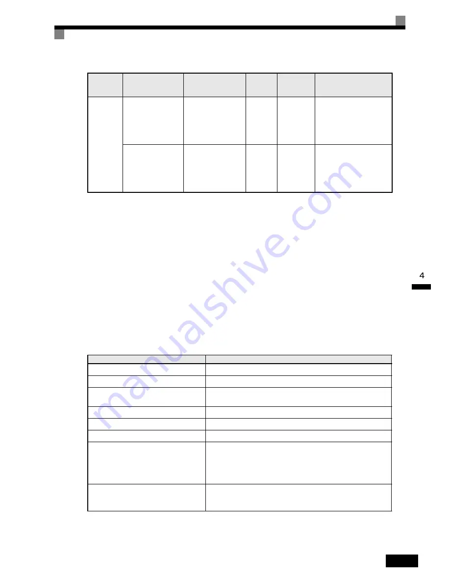
Table 4.7 Parameters Indirectly Affecting Control and Applications
Name (Parameter Number)
Application
CT/VT
selection (C6-01)
Sets
the maximum torque and overload capability to 120% or 150%.
DWELL
function (b6-01 to b6-04)
Used
for heavy loads or large machine backlashes.
Acceleration/deceleration
times
(C1-01
to C1-11)
Adjust
torque during acceleration and deceleration.
S-curve
characteristics (C2-01 to C2-04)
Used
to prevent shock when completing acceleration.
Jump
frequencies (d3-01 to d3-04)
Used
to avoid resonance points during operation.
Analog
input filter time constant (H3-12)
Used
to prevent fluctuations in analog input signals caused by noise.
Stall
prevention (L3-01 to L3-06)
Used
to prevent 0 V (overvoltage errors) and motor stalling for heavy
loads
or rapid acceleration/deceleration. Stall prevention is enabled by
default
and the setting does not normally need to be changed. When using
a
Braking Resistor, however, disable stall prevention during deceleration
by
setting L3-04 to 0.
Torque
limits (L7-01 to L7-04)
Set
the maximum torque during vector control. If a setting is increased,
use
a motor with higher capacity than the Inverter. If a setting is reduced,
stalling
can occur under heavy loads.
Table 4.6 Adjusted Parameters (Continued)
Control
Method
Name (Parameter
Number)
Performance
Factory
Setting
Recom-
mended
Setting
Adjustment Method
Содержание SYSDRIVE 3G3RV
Страница 1: ...USER S MANUAL SYSDRIVE 3G3RV High function General purpose Inverters Cat No I532 E1 1...
Страница 36: ...1 22...
Страница 106: ...3 14...
Страница 126: ...4 20...
Страница 216: ...5 90...
Страница 388: ...7 26...


