


5238-E P-86
SECTION 6 OFFSET FUNCTION
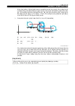
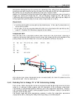
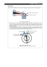
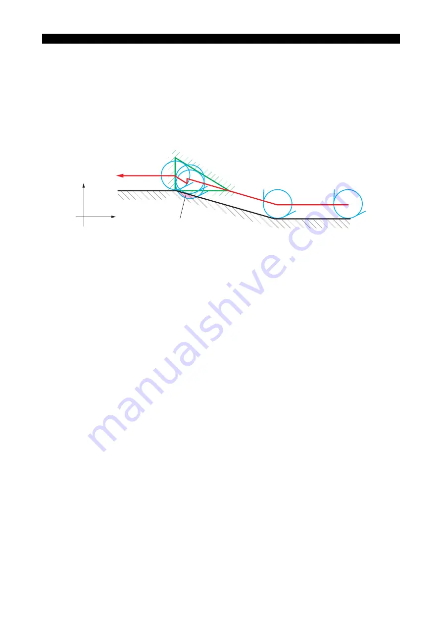
N3, N31 and N32 lie on the same straight line. From N3 to N31, the positioning is on the right hand
side of the line. Commands in block N32 position the cutting tool at the point where the tool nose R
is brought into contact with straight lines N31 - N32 and N3 - N4 on the right side of the direction of
tool advance. This causes the cutting tool to move not only in the X-axis direction but also in the Z-
axis direction although block N32 contains only an X word.
Such cutting tool movements leave an uncut portion as shown above.
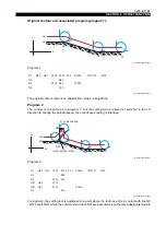
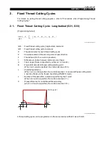
Program 3
In this program, an attempt is made to eliminate the uncut portion caused by program 2.
LE33013R0300800120005
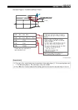
Program 3:
LE33013R0300800120006
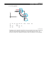
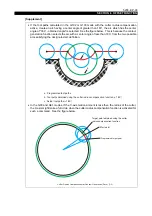
When the control feeds the cutting tool from point N2 to point N3, it reads the position data of point
N31 as well as those of point N3. This permits the tool nose R to be positioned at the point where it
is in contact with the two straight lines N2 - N3 and N3 - N31.
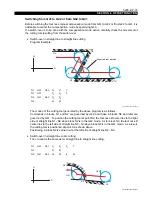
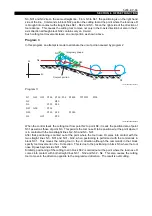
After that, positioning is carried out at the point where the tool nose R comes into contact with the
two straight lines N3 - N31 and N31 - N32, when positioning is performed with the commands in
block N31. This moves the cutting tool in the -X direction although the commands in that block
specify tool movement in the +X direction. This is due to the positioning in block N3, where the tool
nose R goes beyond side N31 - N32.
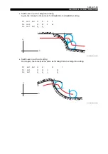
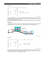
Similarly, positioning of the cutting tool in block N32 is carried out at the point where the tool nose R
comes into contact with both straight lines N31 - N32 and N32 - N4. This also causes the cutting
tool to move in the direction opposite to the programmed direction. The result is overcutting.
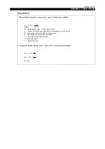
Imaginary shape
Overcut portion
X+
N4
Z+
N31
N3
N32
N2
N1
N1
N2
N3
N31
N32
N4
G42
G00
G01
G01
X100
X120
X124
X120
Z100
Z80
Z40
Z42
Z20
F0.2
S1500
S1000
T010101
M03


