


5238-E P-113
SECTION 7 FIXED CYCLES
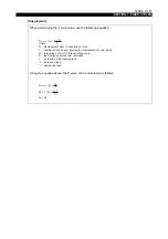
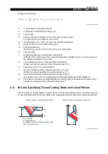
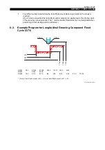
5-4-1. M Codes Specifying Thread Cutting Mode
The thread cutting mode is specified with an M code. The correspondence between modes and M
codes is as follows:
When none of these M codes is specified, the control automatically selects the M32 mode.
If tool angle B is 0
°
, the cutting tool is fed straight independent of the designated cutting mode.
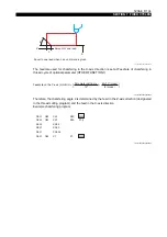
5-4-2. M Codes Specifying the Infeed Pattern
The infeed pattern is specified with an M code. The correspondence between patterns and M codes
is as follows:
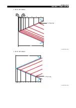
M73: Infeed pattern 1
The amount of infeed is D (diameter value) in each thread cutting cycle up to the point D mm away
from the position "H - U (W)". After that point is reached, the infeed amount is changed to D/2, D/4,
D/8 and D/8, leaving stock removal U (W) if specified. The infeed amount in the finishing cycle is the
specified amount U (W).
When no U (W)word is specified, the finishing cycle is not performed.
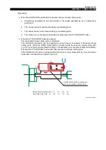
M74: Infeed pattern 2
The amount of infeed is D (in diameter) in each thread cutting cycle until the position "H - U (W)" is
reached. After that, the finishing cycle is carried out with an infeed amount of U (W). If no U (W)
word is specified, the finishing cycle is not performed.
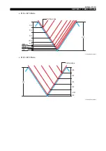
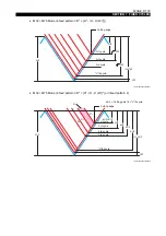
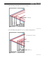
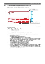
M75: Infeed patterns 3 and 4
In each thread cutting path of the thread cutting cycle, depth of cut is determined so that metal
removal rate is optimum. Infeed pattern 3 or pattern 4 can be selected by the setting at Infeed
pattern in the M75 mode of optional parameter (OTHER FUNCTION 1).
Infeed pattern 3
•
When M32, M34 is designated
D
2
≥
{H
2
- (H - U (W))
2
}
Each thread cutting path in the cycle is determined by the cutting point which is explained as
the depth from the workpiece OD; the first path is created at cutting point "D", the second path
at cutting point "2D", and the "n"th path at cutting point "nD" until the path reaches the cutting
point of "H - U (W)". Finally, the cutting tool is fed by "U (W)" to carry out the finishing cycle.
The finishing cycle is not carried out if U (W) is not designated in the program.
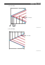
D
2
< {H
2
- (H - U (W))
2
}
In each thread cutting path, assume the thread cutting point d1 (D) and metal removal volume
S
1
for the first path, d
2
and S
2
for the second path, and d
2
and S
n
for the "n"th path, then cutting
points d
2
to dn are determined so that S
2
to S
n
will be the most appropriate metal removal
volume to provide high cutting accuracy while minimizing the number of paths. This cycle is
repeated until the cutting point of "H - U (W)" is reached. Finally, the cutting tool is fed by "U
(W)" to carry out the finishing cycle. The finishing cycle is not carried out if U (W) is not
designated in the program.
M32 : Straight infeed along thread face (on left face)
M33 : Zigzag infeed
M34 : Straight infeed along thread face (on right face)


