


5238-E P-91
SECTION 6 OFFSET FUNCTION
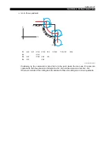
Cutter radius compensation values
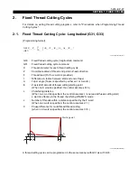
[Function]
The cutter radius compensation values are designated using a 6-digit T command.
LE33013R0300800140001
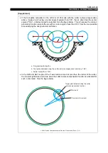
[Details]
•
Set the cutter radius compensation value in advance at the nose R column in the tool data
setting screen.
•
Set the same value for both X and Z. If different values are set, the value having larger absolute
value takes effect.
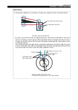
•
The nose R pattern number is effective only in the G18 (nose R compensation) mode. In the
G17 and G119 (cutter radius compensation) modes, it is ignored.
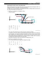
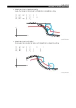
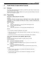
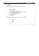
Designation of cutter radius compensation plane and turning on/off the function
•
Before calling the cutter radius compensation function (G41, G42), designate the plane (G17,
G18, G119).
•
When switching the cutter radius compensation direction (G41, G42), cancel the cutter radius
compensation function first by designating G40 before calling the other G code.
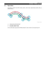
•
To change the compensation plane, cancel the cutter radius compensation function by
designating G40. If G17, G18 or G119 is designated in the G41 or G42 mode, an alarm occurs.
LE33013R0300800140002
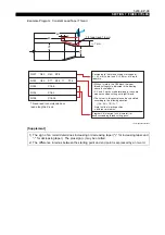
T
Ο Ο ∆ ∆
Ο Ο :
Tool nose radius compensation number
∆ ∆ :
Tool number
:
Tool offset number
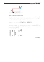
Correct
Wrong
Alarm occurs
G17
G42
G40
G18
G17
G42
G40
G18


