


5238-E P-94
SECTION 6 OFFSET FUNCTION
[Supplement]
In the G00 and G01 modes, the direction of rotation follows the designated command (M15, M16).
In the G101, G102, and G103 modes, the direction of rotation is automatically determined by the
control. Therefore, if M15 is designated because the programmed target point is in the M15
direction viewing from the start point, there may be cases in which the target point calculated using
the cutter radius compensation function comes to lie in the M16 direction. As the result, the C-axis
makes virtually a full circle.
If such a problem occurs, designate the cutter radius compensation function in a different block, or
change the target point.
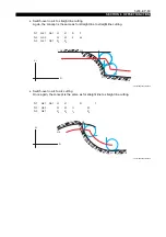
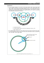
•
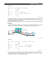
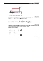
If the cutter radius compensation function is made active for tool paths which run outside the
acute angle shape, there may be cases in which the calculated target point lies far from the
programmed target point. See the figure below.
Target point obtained using the cutter
radius compensation function
Programmed target point
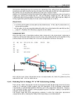
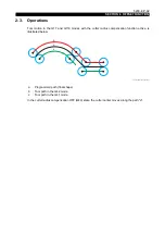
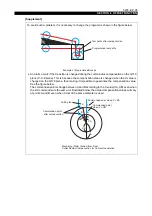
Cutter Radius Compensation for Contour Generation (Side) (2/2)
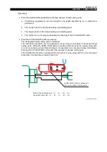
Start point
C
X
Z
Point calculated with cutter radius compensation
Programmed target point


