


5238-E P-251
SECTION 10 COORDINATE SYSTEM CONVERSION
SECTION 10 COORDINATE SYSTEM CONVERSION
1.
Function Overview
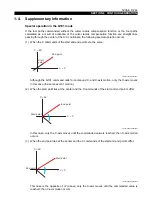
Multiple-machining models have a function to convert the program commands designated in the
Cartesian coordinate system into X and C-axis data in the polar coordinate system on-line.
This function simplifies programming when a hole on the end face of a workpiece is not specified by
the angle but by the vertical distance from a radius vector.
LE33013R0301200010001
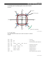
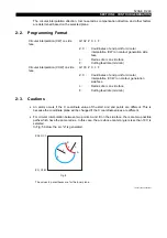
[Programming format]
•
Start of coordinate system conversion
G137 C__ __ __
•
Cancelation of coordinate system conversion
G136
[Details]
•
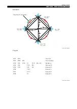
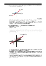
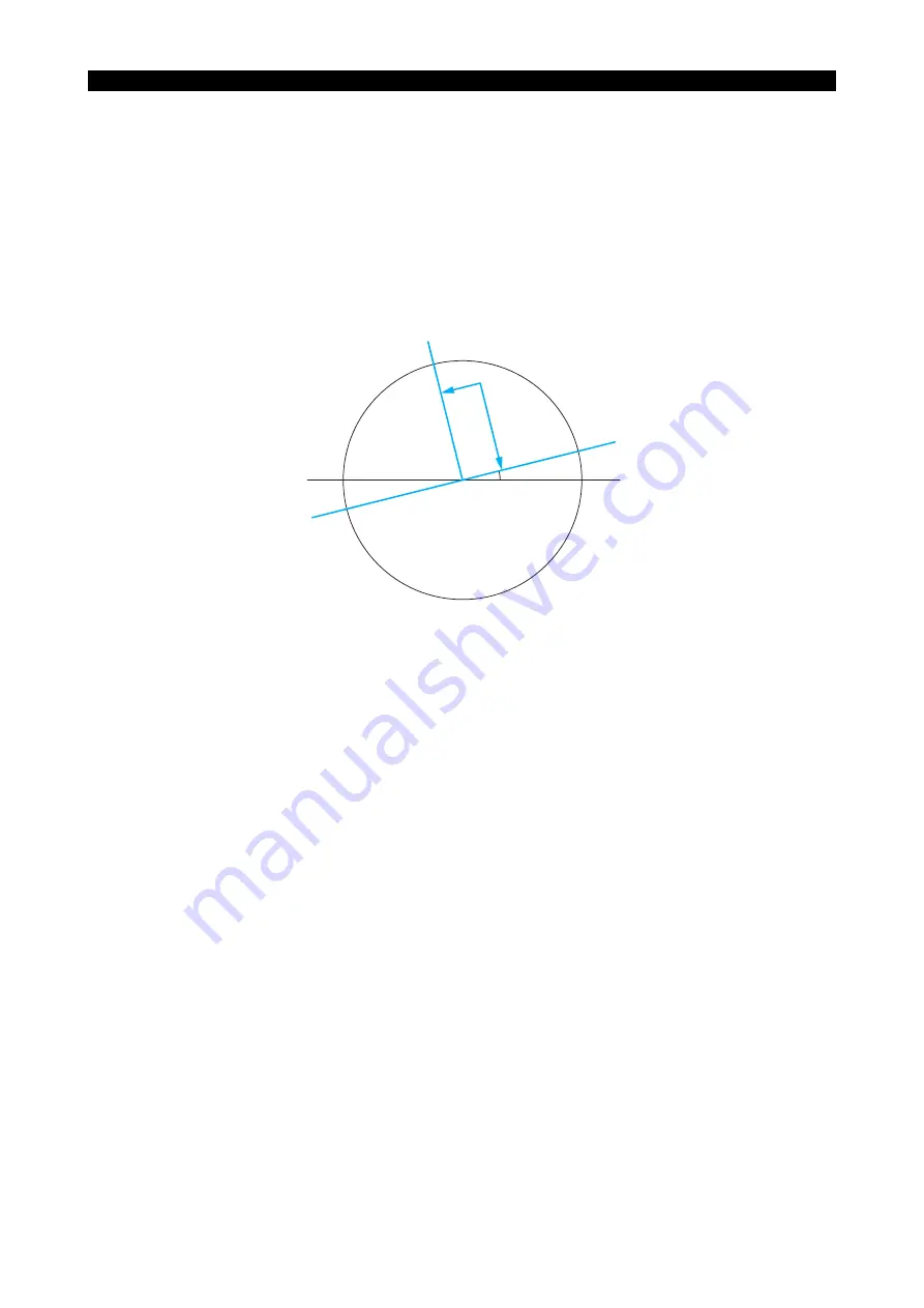
When G137 is designated, a Cartesian coordinate system is set. In this coordinate system, the
Z-axis is taken as the zero point, and the straight line in the direction of angle C designated in
the G137 block is taken as the positive coordinate axis of X.
After the designation, commands are given using the X and Y words instead of using the X and
C words. Values for the X and Y words are given as radius values. Prefix X and Y words of the
specified Cartesian coordinate system with a plus (+) or minus (-) sign.
•
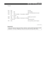
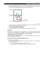
After the completion of positioning using X and Y words in the G137 mode, proceed to
machining. As the machining mode, select a compound fixed cycle or G01.
Since G00, G01, and G codes designating compound fixed cycles are canceled by G137,
designate them in the next block.
•
If the coordinate conversion command is designated while the X- or Z- axis is at its travel end
limit position, an alarm occurs.
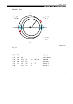
C
: Angle of C-axis that defines the orthogonal coordinate system (
θ
)
First quadrant
: X > 0 Y > 0
Second quadrant : X < 0 Y > 0
Third quadrant : X < 0 Y < 0
Fourth quadrant
: X > 0 Y < 0
+Y
+X
Z
C = 0
°
θ


