5238-E P-297
SECTION 12 USER TASK
4-2.
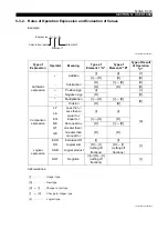
I/O Variables
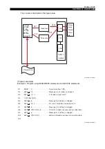
I/O variables are the variables used for sending and receiving I/O signals between the control and
peripheral equipment.
•
Input variables:
The variables representing signals inputted from peripheral equipment such as the operation
panel, the post-process gauging unit, the tool gauging system and the touch sensor.
These signals are called "input bit data".
•
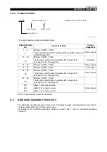
Output variables:
The variables representing signals output from the control to the peripheral equipment such as
indicator lamps and alarm display on the operation panel.
These signals are called "output bit data".
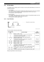
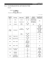
4-2-1. Input Variables
LE33013R0301400400001
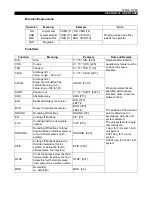
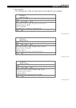
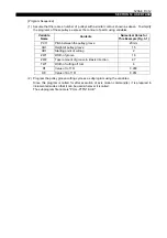
The input variable numbers are tabled below.
Details of specifications must be discussed.
Input Variable
No.
Contents of Data
Input
Equipment
1 ~ 8
Bit data: 0 (OFF), 1 (ON)
Panel input
9
1 byte data in which data of variables #1 through #8 are
corresponded to bit 0 through bit 7.
10
5 bit data of hexadecimal number, $0 through $1F
11 ~ 18
Bit data: 0 (OFF), 1 (ON)
EC input
19
1 byte data in which data of variables #11 through #18
correspond to bit 0 through bit 7.
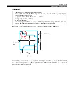
21 ~ 22
Bit data: 0 (OFF), 1 (ON)
Panel input
23 ~ 24
Bit data: 0 (OFF), 1 (ON)
EC input
31 ~ 38
Bit data: 0 (OFF), 1 (ON)
Panel input
39
1 byte data in which data of variables #31 through #38
correspond to bit 0 through bit 7.
1000 ~ 1004
Timers: 1 msec., 1 sec., 1 min., 1 hour, 1 day (timers are reset
to "0" at power on and start counting up after that: 4-byte
counter)
1235 ~ 1250
Condition of specification codes: #1 through #16 (in byte units)
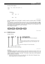
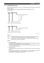
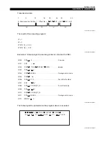
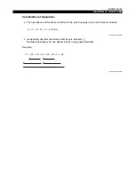
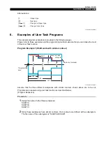
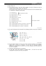
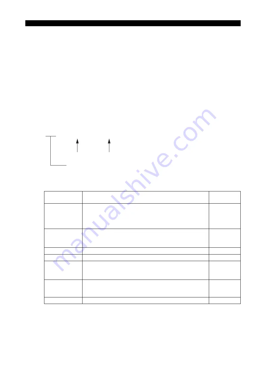
VDIN
[Input variable no.]
Right bracket
Data INput
Left bracket
⋅⋅⋅⋅⋅⋅⋅⋅⋅⋅⋅⋅⋅⋅⋅⋅⋅⋅⋅⋅⋅⋅⋅⋅
Represents an input variable


