


5238-E P-90
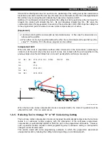
SECTION 6 OFFSET FUNCTION
2.
Cutter Radius Compensation Function
2-1.
Overview
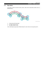
This function automatically offsets the tool paths to generate the required shape in multi-processing
just by programming the final shape.
Using this function, cutters of different diameters can be used to machine workpieces of the same
shape without modifying the program.
2-2.
Programming
Designation of offset plane (G17, G18, G119)
[Function]
Changeover among the X-Z plane (nose R compensation), the X-Y plane (cutter radius
compensation on contour generation machining plane (face)), and C-X-Z plane (cutter radius
compensation on contour generation machining plane (side)) is possible by designating the
appropriate G code.
[Programming format]
[Details]
•
G17 and G119 are effective only while the C-axis is joined.
•
When the C-axis control cancel command (M109) is executed, the X-Z plane (G18) is
automatically selected.
•
When the power is turned on or the control is reset, the X-Z plane (G18) is selected.
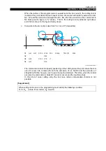
Cutter radius compensation function ON/OFF (G40, G41, G42)
[Function]
Turn the cutter radius compensation function on and off by means of G codes.
[Programming format]
[Details]
•
In the G17 plane, compensation can be activated in the following G code modes.
G00, G01, G101, G102, G103
•
In the G119 plane, compensation can be activated in the following G code modes.
G00, G01, G132, G133
G17
: X-Y plane
(cutter radius compensation on contour generation machining plane, face)
G18
: X-Z plane (nose R compensation)
G119 : C-X-Z plane
(cutter radius compensation on contour generation machining plane, side)
G40 : Cutter radius compensation function OFF
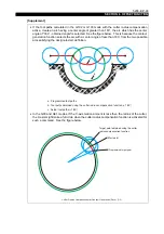
G41 : Cutter radius compensation function, left
(viewed in the direction of tool advance, the tool is positioned at the left side of the
workpiece)
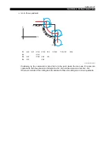
G42 : Cutter radius compensation function, right
(viewed in the direction of tool advance, the tool is positioned at the right side of the
workpiece)


