


5238-E P-114
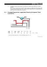
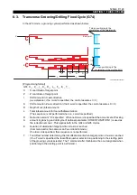
SECTION 7 FIXED CYCLES
•
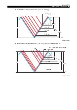
When M33 is designated
D
2
≥
{H
2
- (H - U (W))
2
}
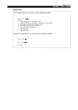
The thread cutting cycle is repeated with the cutting point at each even numbered thread cutting
path being "D" until the cutting point of "H - U (W)" is reached. In each odd numbered tool
paths, the cutting point is calculated as;
LE33013R0300900150001
Finally, the cutting tool is fed by "U (W)" to carry out the finishing cycle. The finishing cycle is
not carried out if U (W) is not designated in the program.
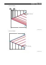
D
2
< {H
2
- (H - U (W))
2
}
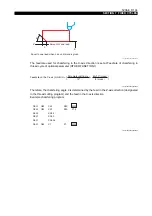
In each thread cutting path, assume the thread cutting point d
1
(D) and metal removal volume
S
1
for the first path, d
2
and S
2
for the second path, and d
n
and S
n
for the "n"th path, then cutting
points d
2
to d
n
(n = even number) for the even numbered paths are determined so that S
2
to S
n
(n = even number) will be the most appropriate metal removal volume to provide high cutting
accuracy while minimizing the number of paths. For the odd numbered paths, the cutting point
is determined by
d
n
= 1/2 (d
n-1
+ d
n+1
) (d = odd number).
This cycle is repeated until the cutting point of "H - U (W)" is reached. Finally, the cutting tool is
fed by "U (W)" to carry out the finishing cycle. The finishing cycle is not carried out if U (W) is
not designated in the program.
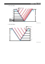
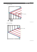
Infeed pattern 4
•
When M32, M34 is designated
The following pattern is created regardless of the values of H, D, and U(W).
In each thread cutting path, assume the thread cutting point d
1
(D) and metal removal volume
S
1
for the first path, d
2
and S
2
for the second path, and dn and Sn for the "n"th path, then cutting
points d
2
to d
n
are determined so that S
2
to S
n
will be the most appropriate metal removal
volume to provide high cutting accuracy while minimizing the number of paths. This cycle is
repeated until the cutting point of "H - U (W)" is reached. Finally, the cutting tool is fed by "U
(W)" to carry out the finishing cycle. The finishing cycle is not carried out if U (W) is not
designated in the program.
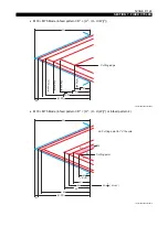
•
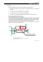
When M33 is designated
In each thread cutting path, assume the thread cutting point d
1
(D) and metal removal volume
S
1
for the first path, d
2
and S
2
for the second path, and dn and d
n
for the "n"th path, then cutting
points d
2
to d
n
(n = even number) for the even numbered paths are determined so that S
2
to S
n
(n = even number) will be the most appropriate metal removal volume to provide high cutting
accuracy while minimizing the number of paths. For the odd numbered paths, the cutting point
is determined by
d
n
= 1/2 (d
n-1
+ d
n+1
) (d = odd number).
This cycle is repeated until the cutting point of "H - U (W)" is reached. Finally, the cutting tool is
fed by "U (W)" to carry out finishing cycle. The finishing cycle is not carried out if U (W) is not
designated in the program.
[Supplement]
Since X commands are specified as diameter values, the actual infeed amount is "D/2".
When no infeed-pattern-designating M code is programmed, the control automatically selects
M73.
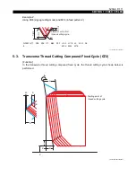
By combining the M codes designating cutting mode and infeed pattern, ten types of thread cutting
cycle each are available for longitudinal thread cutting and transverse thread cutting.
( n + 1
D +
n - 1
D )
1
2


