


5238-E P-42
SECTION 4 PREPARATORY FUNCTIONS
2-2.
Max. Spindle Speed Set
[Function]
Sometimes the spindle speed must be clamped at a certain speed due to the restrictions on the
allowable speed of a chuck, influence of centrifugal force on workpiece gripping force, imbalance of
a workpiece, or other factors. This feature allows a maximum spindle speed to be set in such cases.
[Programming format]
G50 S__
[Details]
Once set, the specified speed remains effective until another spindle speed is specified.
3.
Droop Control (G64, G65)
[Function]
The axis movements of the machine are controlled by a servo system in which the axis moves to
eliminate the lag (termed DIFF or droop) between the actual tool position and the commanded
coordinate.
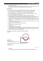
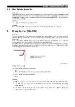
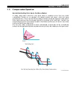
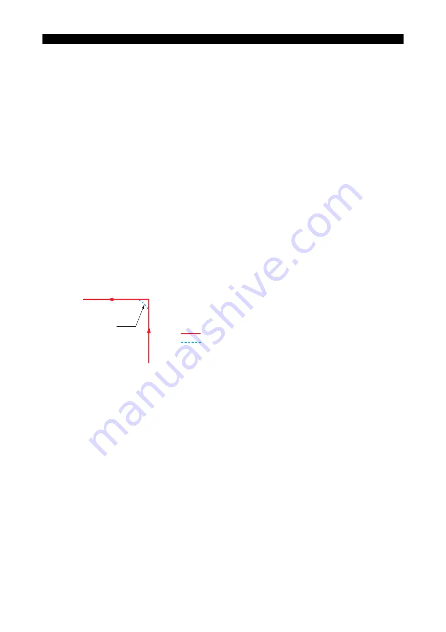
Due to existence of DIFF (servo error), the actual path does not precisely agree with the
commanded tool path when cutting a sharp corner, as illustrated below:
The Droop Corner Control Function is provided to eliminate or reduce such path tracing error to
acceptable amounts by stopping the generation of functions (pulses) at the corner until the DIFF
reaches the preset permissible droop amount.
LE33013R0300600050001
[Programming format]
•
Droop corner control OFF command
G64
(The control is placed in the G64 mode when G64 is turned ON.)
•
Droop corner control ON command
G65
[Details]
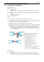
•
With G65 presented, axis movement commands in G00, G01, G02, G03, G31, G32, G33, G34,
and G35 mode are completed after the DIFF amount becomes smaller than the permissible
droop amount.
•
The permissible droop amount can be set within a range from 0 to 1.000 mm for a user
parameter at the NC operation panel.
S
: Specify the maximum spindle speed.
Droop
Programmed tool path
Actual tool path


