


5238-E P-204
SECTION 8 LATHE AUTO-PROGRAMMING FUNCTION (LAP)
If M85 is designated in this block, tool retraction to the AP starting point at the completion of
rough turning can be canceled. This eliminates unnecessary tool motion which is generated
when the same tool is used in the next machining process.
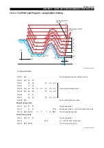
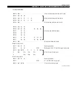
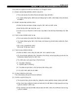
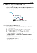
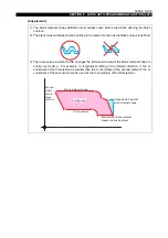
To change the cutting conditions during the rough turning cycle, designate the following
commands with G84.
To change the cutting conditions again, designate the following commands.
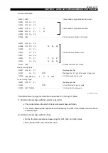
Cutting condition change point(s) must be programmed in the block containing G85. For clear
programming, commands related with such point(s) are programmed in different lines, each line
preceded by the $ character which indicates that it is a continuation of the preceding line.
When an F word is not designated in this block, the feedrate commanded last is effective.
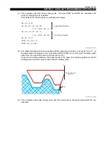
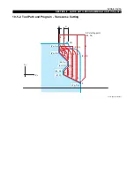
Point data of cutting condition change point(s) must become smaller in the order AP starting
point (Xs), then XA and then XB for OD turning. For ID turning, they must become larger in this
order.
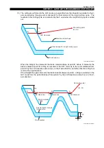
(4) The commands between G83 and G81 are taken as the commands to define the blank material
shape, and the commands between G81 and G80 are taken as the commands to define the
finish contour.
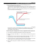
For OD turning, draw the perpendicular from the point which is obtained by shifting the point on
the maximum OD of the blank material shape or final rough turning contour, whichever is larger,
and obtain the point of intersection A of this perpendicular with the blank material shape.
For ID turning, draw the perpendicular from the point which is obtained by shifting the point on
the minimum ID of the blank material shape or final rough turning contour, whichever is smaller.
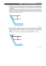
The cutting tool is positioned at the point distanced from point A by the LAP clearance amount
(Lc) in the Z-axis direction. Positioning is performed at the rapid feedrate when G00 is
designated in the first block of the finish contour definition blocks, and at a cutting feedrate
when G01 is designated in the first block of these blocks.
•
The LAP clearance amount (Lc) is set at LAP clearance amount of optional parameter
(OTHER FUNCTION 1) in units of 0.01 mm.
•
For the relationship between the LAP clearance amount and the AP starting point, refer to
10-4-5 "How to Obtain the Infeed Starting Point".
•
An alarm occurs if the G02 or G03 code is specified in the first block of the blocks used to
define the blank workpiece shape.
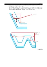
XA : X coordinate of cutting condition change point A
DA : Depth of cut after point A
FA
: Feedrate after point A
XB : X coordinate of cutting condition change point B
DB : Depth of cut after point B
FB : Feedrate after point B


