3. SIGNALS AND WIRING
3 - 39
3.13 Control axis selection
POINT
The control axis number set to rotary axis setting switch (SW1) should be the same
as the one set to the servo system controller.
For changing the setting of the rotary switch, use a flat-blade screwdriver with the
blade edge width of 2.1 to 2.3 [mm] and the blade edge thickness of 0.6 to 0.7
[mm].
When the test operation mode is selected by using the test operation select switch
(SW2-1), the SSCNET communication for the servo amplifier in the test
operation mode and the following servo amplifiers is blocked.
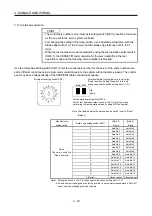
Use the rotary axis setting switch (SW1) to set the control axis number for the servo. If the same numbers are
set to different control axes in a single communication system, the system will not operate properly. The control
axes may be set independently of the SSCNET cable connection sequence.
0
8
7
6
5
4
3
2
1
F
E
D
C
B
A
9
Rotary axis setting switch(SW1)
Down
Up
Test operation select switch (SW2-1)
Set the test operation select switch to the "Up" position, when
performing the test operation mode by using MR Configurator.
For manufacturer setting (Be sure to set to the
"Down" position. Setting the switch to the "Up"
position causes the switch setting error (11.2).)
(Note) SW2
Note. This table indicates the status when the switch is set to "Down".
(Default)
Manufacturer
setting switch
Rotary axis setting switch (SW1)
(Note 2)
A-axis
(Note 2)
B-axis
0
Axis No.1
Axis No.2
1
Axis No.2
Axis No.3
2
Axis No.3
Axis No.4
3
Axis No.4
Axis No.5
4
Axis No.5
Axis No.6
5
Axis No.6
Axis No.7
6
Axis No.7
Axis No.8
7
Axis No.8
Axis No.9
8
Axis No.9
Axis No.10
9
Axis No.10
Axis No.11
A
Axis No.11
Axis No.12
B
Axis No.12
Axis No.13
C
Axis No.13
Axis No.14
D
Axis No.14
Axis No.15
E
Axis No.15
Axis No.16
Down
(Be sure to set to the
"Down" position.)
F (Note 1)
Cannot be set Cannot be set
Note 1. Setting the switch to the "F" position causes the switch setting error (11.1).
2. An axis number is assigned even for the axis that is set as motor-less operation. Set SW1
so as to avoid overlapping the axis numbers.
Содержание MELSERVO-J3W Series
Страница 17: ...8 MEMO ...
Страница 27: ...1 FUNCTIONS AND CONFIGURATION 1 10 MEMO ...
Страница 87: ...4 STARTUP 4 14 MEMO ...
Страница 117: ...5 PARAMETERS 5 30 MEMO ...
Страница 129: ...6 GENERAL GAIN ADJUSTMENT 6 12 MEMO ...
Страница 185: ...10 CHARACTERISTICS 10 8 MEMO ...
Страница 241: ...11 OPTIONS AND AUXILIARY EQUIPMENT 11 56 MEMO ...
Страница 274: ...13 USING A LINEAR SERVO MOTOR 13 25 1 2 3 4 ...


