15. MR-J3W-0303BN6 SERVO AMPLIFIER
15 - 33
When switching power on for the first time, follow this section to make a startup.
15.4.1 Startup procedure
Wiring check
Surrounding environment check
Axis No. settings
Parameter setting
Test operation of servo motor
alone in test operation mode
Test operation of servo motor
alone by commands
Test operation with servo motor
and machine connected
Gain adjustment
Actual operation
Stop
Setting of main circuit power
supply voltage
Check that the parameter No.Po04 is set to the input voltage for the main circuit
power supply. 24VDC: 1
, 48VDC/24VDC: 0
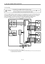
Check whether the servo amplifier and servo motor are wired correctly using
visual inspection, DO forced output function (section 4.5.1), etc. (Refer to section
15.4.3.)
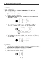
Check the surrounding environment of the servo amplifier and servo motor.
(Refer to section 15.4.4.)
Confirm that the axis No. settings for rotary axis setting switch (SW1) and servo
system controller are consistent. (Refer to section 3.13.)
Set the parameters as necessary, such as the control mode. (Refer to chapter
5.)
For the test operation, with the servo motor disconnected from the machine and
operated at the speed as low as possible, check whether the servo motor rotates
correctly. (Refer to section 4.5.)
For the test operation with the servo motor disconnected from the machine and
operated at the speed as low as possible, give commands to the servo amplifier
and check whether the servo motor rotates correctly.
After connecting the servo motor with the machine, check machine motions with
sending operation commands from the controller.
Make gain adjustment to optimize the machine motions. (Refer to chapter 6.)
Stop giving commands and stop operation.
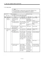
15.4.2 Troubleshooting during "24V ERROR" lamp on.
(1) When Overvoltage is applied to the control circuit in the servo amplifier, power supply to the circuit will be
shut off and the "24V ERROR" lamp will turn on. Then, the 3-digit, 7-segment LED on display will turn off.
Immediately turn off the power and check the wiring, etc. to the main circuit power supply (48VDC).
(2) If the "24V ERROR" lamp turned on with the 3-digit, 7-segment LED on, the control circuit power supply
voltage (24VDC) may be failure. Check that the voltage of the control circuit power supply is 21.6V or more.
Содержание MELSERVO-J3W Series
Страница 17: ...8 MEMO ...
Страница 27: ...1 FUNCTIONS AND CONFIGURATION 1 10 MEMO ...
Страница 87: ...4 STARTUP 4 14 MEMO ...
Страница 117: ...5 PARAMETERS 5 30 MEMO ...
Страница 129: ...6 GENERAL GAIN ADJUSTMENT 6 12 MEMO ...
Страница 185: ...10 CHARACTERISTICS 10 8 MEMO ...
Страница 241: ...11 OPTIONS AND AUXILIARY EQUIPMENT 11 56 MEMO ...
Страница 274: ...13 USING A LINEAR SERVO MOTOR 13 25 1 2 3 4 ...


