3. SIGNALS AND WIRING
3 - 32
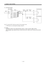
(1) Connection diagram
24VDC power
supply for
electromagnetic
brake
A-axis servo motor
Servo amplifier
DICOM
ALM-A
DOCOM
24VDC
MBR-A
EM1
DICOM
RA1
RA2
B
(Note 2)
RA5
B2
U
B1
EM1
RA3
RA4
ALM-B
MBR-B
B-axis servo motor
B
B2
U
B1
ALM-A
RA1
MBR-A
RA2
ALM-B
RA3
MBR-B
RA4
(Note 1)
Note 1. Do not use the 24VDC interface power supply for the electromagnetic brake.
2. Shut off the circuit by interlocking with the emergency stop switch.
(2) Setting
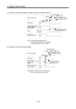
In parameter No.PC02 (electromagnetic brake sequence output), set the time delay (Tb) from
electromagnetic brake operation to base circuit shut-off at a servo off time as in the timing chart in section
3.11.2.
Содержание MELSERVO-J3W Series
Страница 17: ...8 MEMO ...
Страница 27: ...1 FUNCTIONS AND CONFIGURATION 1 10 MEMO ...
Страница 87: ...4 STARTUP 4 14 MEMO ...
Страница 117: ...5 PARAMETERS 5 30 MEMO ...
Страница 129: ...6 GENERAL GAIN ADJUSTMENT 6 12 MEMO ...
Страница 185: ...10 CHARACTERISTICS 10 8 MEMO ...
Страница 241: ...11 OPTIONS AND AUXILIARY EQUIPMENT 11 56 MEMO ...
Страница 274: ...13 USING A LINEAR SERVO MOTOR 13 25 1 2 3 4 ...


