15. MR-J3W-0303BN6 SERVO AMPLIFIER
15 - 12
24
0
PM
Servo amplifier
U
V
W
CNP1
CNP2A
A-axis servo motor
U
V
W
M
Motor
Encoder
CN2A
(Note 2)
Encoder cable
(Note 5)
EM1
DOCOM
(Note 6) Forced stop
CN3
(Note 4)
ALM-A
DICOM
DOCOM
24VDC
A-axis malfunction
(Note 3)
CN3
U
V
W
B-axis servo motor
U
V
W
M
Encoder
CN2B
(Note 2)
Encoder cable
(Note 5)
ALM-B
(Note 4)
B-axis malfunction
(Note 3)
RA1
RA2
Circuit
protector
OFF
RA4
ON
RA1(A-axis)
RA2(B-axis)
Controller
forced stop
RA3
Forced stop
(Note 6)
(Note 3)
RA4
(Note 7)
(Note 8)
CNP2B
24VDC
(Note 1)
48VDC
(Note 1)
Main circuit power
supply: 48VDC
Circuit
protector
24VDC
(Note 1)
Main circuit power
supply: 24VDC
RA4
Malfunction
(Note 7)
Motor
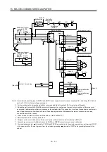
Note 1. Use reinforced insulating type for 24VDC and 48VDC power supply. Connect at power supply part for - side wiring (0V). Refer to
section 15.3.3 (1) (c) for selecting power supply.
2. For the encoder cable, using optional cable is recommended. Refer to section 15.9.1 for selection of the cable.
3. If disabling malfunction (ALM-A/ALM-B) output with the parameter, configure up the circuit which switches off the main circuit
power supply after detection of alarm occurrence on the controller side. This example is to continue the operation in another axis
even if an alarm occurs either A-axis or B-axis. When stopping operation of both axes at an alarm occurrence for one axis,
connect RA1 and RA2 in series.
4. This is for sink I/O interface. For source I/O interface, refer to section 3.7.3.
5. Refer to section 15.3.6 for wiring power lines.
6. Configure up the circuit which shuts off main circuit power with external circuit at forced stop 1 (EM1) off.
7. Connecting a servo motor for different axis to the CNP2A or CNP2B connector may cause a malfunction.
8. The noiseless grounding (
) terminals of CNP2A and CNP2B are connected to the noiseless grounding (
) terminal of CNP1
in the servo amplifier. Be sure to ground from the noiseless grounding (
) terminal of CNP1 to the grounding terminal of the
cabinet.
Содержание MELSERVO-J3W Series
Страница 17: ...8 MEMO ...
Страница 27: ...1 FUNCTIONS AND CONFIGURATION 1 10 MEMO ...
Страница 87: ...4 STARTUP 4 14 MEMO ...
Страница 117: ...5 PARAMETERS 5 30 MEMO ...
Страница 129: ...6 GENERAL GAIN ADJUSTMENT 6 12 MEMO ...
Страница 185: ...10 CHARACTERISTICS 10 8 MEMO ...
Страница 241: ...11 OPTIONS AND AUXILIARY EQUIPMENT 11 56 MEMO ...
Страница 274: ...13 USING A LINEAR SERVO MOTOR 13 25 1 2 3 4 ...


