


17
Function library
17.1
Function blocks | L_Interpolator_1
1397
Lenze · 8400 HighLine · Reference manual · DMS 12.0 EN · 06/2017 · TD23
_ _ _ _ _ _ _ _ _ _ _ _ _ _ _ _ _ _ _ _ _ _ _ _ _ _ _ _ _ _ _ _ _ _ _ _ _ _ _ _ _ _ _ _ _ _ _ _ _ _ _ _ _ _ _ _ _ _ _ _ _ _ _ _
17.1.95.3 Angle correction in case of transmission errors
If an angular offset between master and slave is caused due to transmission errors (missing data
telegrams), it will be corrected by a catch-up function in the FB. For this purpose, the following
connections and parameter settings are required for the slave at the FB
L_Interpolator_1
:
1. The master angle of the master is connected to the
dnPhiIn_p
input.
2. The speed signal of the master is connected to the
nNIn_a
input.
3. The
nNOut_a
output is connected to the
nSet_v
input of the FB
.
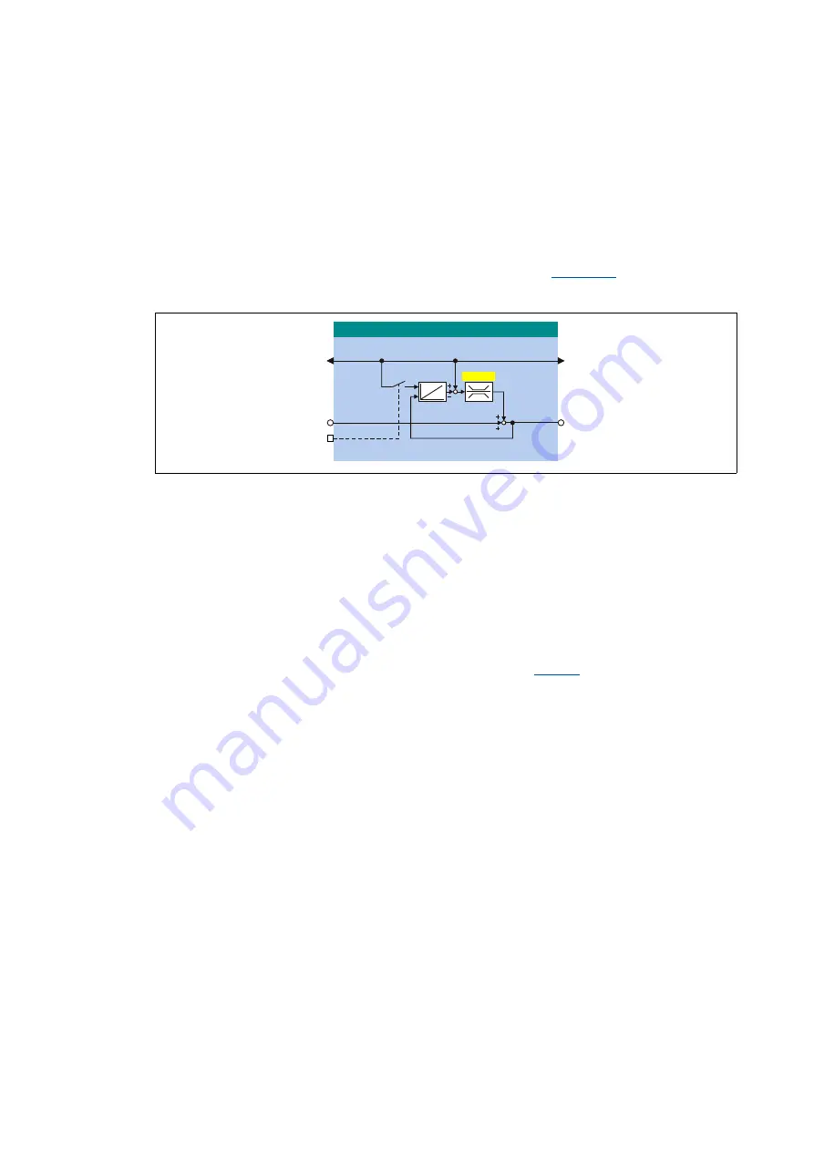
The following illustration shows the principle of the catch-up function in the FB
L_Interpolator_1
:
[17-42] Principle of the catch-up function
The speed signal at
nNIn_a
is provided almost 1:1 at the
nNOut_a
output. In case of a telegram
error, a correction value can be added to the signal. This correction value results from the
subtraction of the integrated speed signal from the position value applied at
dnPhiIn_p
.
If, for example, a data telegram should fail, the input values remain constant for one program cycle.
During the next cycle, the correct position and the correct speed are restored.
"Holding" the position at
dnPhiIn_p
results in a difference between the position values at
dnPhiIn_p
and at the output of the integrator. This difference is added to the
nNOut_a
output signal.
In order that this angle correction does not lead to a strong jerk in the master value, the amount of
correction increments is limited per cycle (catch-up cycle) using
. A typical correction value
is for instance 10 increments/ms.
When the controller is inhibited, the integrator is to be loaded with the position value pending at
dnPhiIn_p
by setting the
bSpeedAct0
input to TRUE. When the controller is enabled, the
nNOut_a
speed signal is integrated.
/B,QWHUSRODWRUB
GQ3KL2XWBS
GQ3KL,QBS
Q1,QBD
E6SHHG$FW
Q12XWBD
& 6SHHGXS