iii
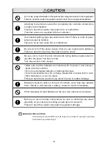
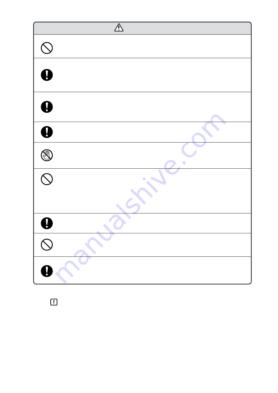
CAUTION
Be sure to turn off the power supply when you are replacing the batteries.
Failure to heed this warning may lead to electric shock.
When disposing of used batteries at the user site, observe local bylaws.
Before you touch internal components, be sure to discharge any static
electricity on your body by touching a metal ground connector.
Failure to heed this caution may lead to equipment damage.
Batteries should be kept out of reach of children, since they may swallow
them. Should a child swallow a battery, contact a doctor immediately.
HANDLING PRECAUTIONS
After turning on the DCP551 mark
ΙΙ
, leave it for at least 10 seconds to let it sta-
bilize before you start using it.
Attaching the terminal covers after completing the controller connections
is highly recommended.
Failure to heed this caution may lead to fire or malfunction.
(Terminal covers are supplied with the controller.)
• Make sure that the batteries are inserted with the plus(+) and minus(–)
poles correctly oriented.
• Do not use damaged batteries or batteries that leak.
• Do not throw batteries into a fire, recharge, disassemble or expose them to heat.
• Store batteries in a cool, dry place.
Failure to heed these cautions may result in burns or battery leakage.
Be sure not to touch internal components during battery replacement or
just after the power has been turned.
This may result in burn injuries.
Do not use unused terminals on the instrument as relay terminals for other equipment.
Failure to heed this caution may lead to electric shock, fire or equipment breakdown.
Use induced lighting surge preventive device Non if there is a risk of power
surges caused by lighting.
Failure to do so may cause fire or malfunction.
Содержание DCP550
Страница 1: ...EN1I 6186 Issue 13 04 08 DCP551 Mark ΙΙ Digital Control Programmer User s Manual www honeyvell energy ...
Страница 115: ...Chapter 7 PARAMETER SETUP Settings by event type For information on event operations see Events pages 5 5 to 5 15 7 13 ...
Страница 117: ...Chapter 7 PARAMETER SETUP 0 1 02 3 02 3 0 1 1 4 5 1 4 6 1 4 5 2 2 2 7 15 ...
Страница 119: ...Chapter 7 PARAMETER SETUP 0 11 2 2 3 3 7 17 ...
Страница 122: ...Chapter 7 PARAMETER SETUP d A5 tP A5 CP A5 rE A5 P A6 I A6 d A6 rE A6 CP A6 tP A6 P A7 I A7 d A7 rE A7 CP A7 tP A7 7 20 ...
Страница 209: ...Chapter 12 CALIBRATION Figure 12 11 Current Outputs 12 18 ...
Страница 229: ......
Страница 230: ...No CP UM 5024E ...


