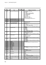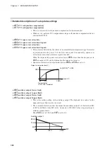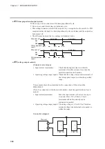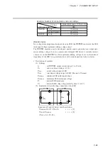
Chapter 8. PROGRAM SETUP
■
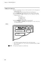
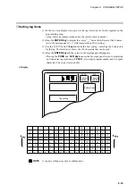
Display items
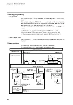
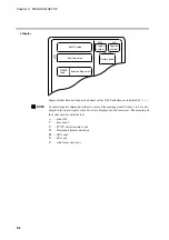
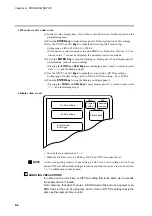
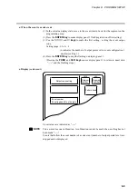
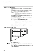
Items displayed are shown in the figure below.
■
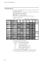
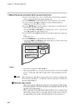
Setting pattern items
(1) In the set value display state, move to the segment pattern item to be set on the pro-
gramming map.
(2) Press the
ENTER key
to make display panel 1 flash (registration of first setting).
(3) Use the
↑
,
↓
,
←
, and
→
keys
to set the first setting (SP).
Setting range: SP limit lower limit to upper limit
(SP limit is set using setup data
C66
and
C67
.)
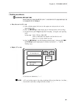
(4) Pressing the
ENTER key
stops display panel 1 from flashing and causes display
panel 2 to start flashing. (This starts start registration of the second setting.) Instead
of pressing the
ENTER key
, press the
FUNC
and
ENTER keys
to switch between
RAMP types (selecting RAMP-X
⇔
RAMP-T, or RAMP-X
⇔
RAMP-E is made
with setup data
C61
).
(5) Use the
↑
,
↓
,
←
, and
→
keys
to make the second setting (time).
Setting range: 0:00 to 500:00, 0.0 to 3000.0
(Time units are selected using setup data
C62
to set Hour/min, Min/sec, 0.1 sec.
Since a colon “:” cannot be displayed, the decimal point is used instead.)
(6) Press the
ENTER key
to stop display panel 2 from flashing.
!
"
#
"
! " $
! " %
& !
8-5
Содержание DCP550
Страница 1: ...EN1I 6186 Issue 13 04 08 DCP551 Mark ΙΙ Digital Control Programmer User s Manual www honeyvell energy ...
Страница 115: ...Chapter 7 PARAMETER SETUP Settings by event type For information on event operations see Events pages 5 5 to 5 15 7 13 ...
Страница 117: ...Chapter 7 PARAMETER SETUP 0 1 02 3 02 3 0 1 1 4 5 1 4 6 1 4 5 2 2 2 7 15 ...
Страница 119: ...Chapter 7 PARAMETER SETUP 0 11 2 2 3 3 7 17 ...
Страница 122: ...Chapter 7 PARAMETER SETUP d A5 tP A5 CP A5 rE A5 P A6 I A6 d A6 rE A6 CP A6 tP A6 P A7 I A7 d A7 rE A7 CP A7 tP A7 7 20 ...
Страница 209: ...Chapter 12 CALIBRATION Figure 12 11 Current Outputs 12 18 ...
Страница 229: ......
Страница 230: ...No CP UM 5024E ...


