


Chapter 4. WIRING
4-1 Precautions on Wiring
4-1
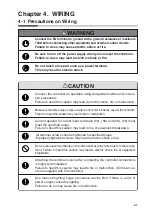
WARNING
Connect the FG terminal to ground with a ground resistance of maximum
100
Ω
before connecting other equipment and external control circuits.
Failure to do so may cause electric shock or fire.
Be sure to turn off the power supply when you connect the controller.
Failure to do so may lead to electric shock or fire.
Do not touch a live part such as a power terminal.
This may result in electric shock.
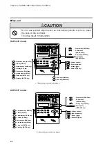
CAUTION
Make sure that wire scraps, chips or water do not enter inside the case of the controller.
Failure to heed this caution may lead to fire or malfunction.
All terminal screws shall be tightened to specified torque.
Improperly tightened screws may lead to electric shock or fire.
Connect the controller as specified using designated cables and connec-
tion procedures.
Failure to heed this caution may lead to electric shock, fire or malfunction.
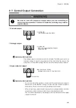
Current applied to current input terminals (55), (56) and (58), (59) must
meet the specified range.
Failure to heed this caution may lead to fire or equipment breakdown.
Do not use unused terminals on the instrument as relay terminals for other equip-
ment. Failure to heed this caution may lead to electric shock, fire or equipment
breakdown.
Attaching the terminal covers after completing the controller connections
is highly recommended.
Failure to heed this caution may lead to fire or malfunction. (Terminal cov-
ers are supplied with the controller.)
Use induced lighting surge preventive device Non if there is a risk of
power surges caused by lighting.
Failure to do so may cause fire or malfunction.
Содержание DCP550
Страница 1: ...EN1I 6186 Issue 13 04 08 DCP551 Mark ΙΙ Digital Control Programmer User s Manual www honeyvell energy ...
Страница 115: ...Chapter 7 PARAMETER SETUP Settings by event type For information on event operations see Events pages 5 5 to 5 15 7 13 ...
Страница 117: ...Chapter 7 PARAMETER SETUP 0 1 02 3 02 3 0 1 1 4 5 1 4 6 1 4 5 2 2 2 7 15 ...
Страница 119: ...Chapter 7 PARAMETER SETUP 0 11 2 2 3 3 7 17 ...
Страница 122: ...Chapter 7 PARAMETER SETUP d A5 tP A5 CP A5 rE A5 P A6 I A6 d A6 rE A6 CP A6 tP A6 P A7 I A7 d A7 rE A7 CP A7 tP A7 7 20 ...
Страница 209: ...Chapter 12 CALIBRATION Figure 12 11 Current Outputs 12 18 ...
Страница 229: ......
Страница 230: ...No CP UM 5024E ...