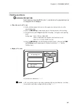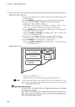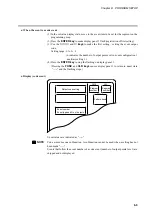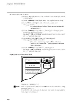
Chapter 7. PARAMETER SETUP
●
C52
(SP output lower limit)
●
C53
(SP output upper limit)
These are scaling settings of SP output. The high and low values for the upper and lower
limits can be reversed.
●
C63
(time display)
0: remaining segment time
1: total operation time
• These are selections for display panel 2 in the normal display mode in the program
run mode.
• In the READY mode a setting of 0 displays the set time values for the selected seg-
ments.
• In the RUN, HOLD, FAST and END modes a setting of 0 displays the remaining
time in rounded hours.
For example, when the time unit hours/min is selected a remaining time of 1 hour 30
minutes and 59 seconds is displayed as “
1.30
”.
• In the READY mode a setting of 1 displays the time as “
0.00
”.
• In the RUN, HOLD, FAST and END modes a setting of 1 means that the time is dis-
played in rounded hours after a change from the READY mode to the RUN mode. In
G.SOAK wait, repeat, cycle and pattern link, time is displayed as integrated values.
When the time unit is hours/min or min/sec, the display returns to “
0.00
” after
“
499.59
”. When the time unit is 0.1 sec, the display returns to “
0.0
” after
“
2999.9
”.
When the time unit is hour/min, a total operating time of 501 hours 30 minutes and 59
seconds is displayed as “
1.30
”.
• In FAST mode a setting of 0 or 1 displays the time according to FAST X.
●
C66
(SP limit lower limit)
●
C67
(SP limit upper limit)
• These settings operate as limiters when SP is set or changed in the program setting
pattern items.
• In the program run mode these settings operate as limiters when SP and SP bias (vari-
able parameter) set in a program are added to produce the resulting SP.
• These settings operate as limiters when SP is set or changed in constant value control
data settings.
• In the constant value control mode these settings operate as limiters when SP and SP
bias (variable parameter) set in constant value control data settings are added to pro-
duce the resulting SP.
7-29
Содержание DCP550
Страница 1: ...EN1I 6186 Issue 13 04 08 DCP551 Mark ΙΙ Digital Control Programmer User s Manual www honeyvell energy ...
Страница 115: ...Chapter 7 PARAMETER SETUP Settings by event type For information on event operations see Events pages 5 5 to 5 15 7 13 ...
Страница 117: ...Chapter 7 PARAMETER SETUP 0 1 02 3 02 3 0 1 1 4 5 1 4 6 1 4 5 2 2 2 7 15 ...
Страница 119: ...Chapter 7 PARAMETER SETUP 0 11 2 2 3 3 7 17 ...
Страница 122: ...Chapter 7 PARAMETER SETUP d A5 tP A5 CP A5 rE A5 P A6 I A6 d A6 rE A6 CP A6 tP A6 P A7 I A7 d A7 rE A7 CP A7 tP A7 7 20 ...
Страница 209: ...Chapter 12 CALIBRATION Figure 12 11 Current Outputs 12 18 ...
Страница 229: ......
Страница 230: ...No CP UM 5024E ...

