7-24
Chapter 7. PARAMETER SETUP
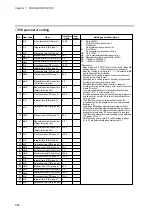
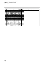
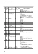
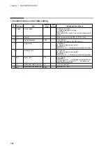
0: Continues until power is turned off
1: PV1
2: PV2
3: High-temperature PV
4: Low-emperature PV
[Description:]
Ò-----Ó is displayed and setting cannot be performed on
model with one PV input channel.
When
C25
is set to more than 1, Ò-----Ó is displayed and
setting cannot be performed.
When
C26
is set 0, Ò-----Ó is displayed and setting cannot be
performed.
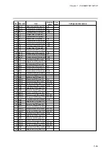
0
C 29
29
Selections available when
power is on during PV
channel switching
1 to 1000 PVU (PV1)
[Description:]
Ò-----Ó is displayed and setting cannot be performed on
model with one PV input channel.
When
C25
is set to more than 1, Ò-----Ó is displayed and
setting cannot be performed.
When
C26
is set 0, Ò-----Ó is displayed and setting cannot be
performed.
100 PVU
C 28
28
PV channel switching dead
band
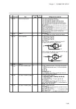
0: No
1: PV1 only
2: PV2 only
3: PV1 and PV2
[Description:]
The range of settings is 0 to 1 on model with one PV
input channel.
0
C 30
30
PV equalizer
0: READY mode
1: ENDmode
0
C 31
31
End of operation
0: No
1: Yes
0
C 33
33
Manipulated variable setting
in PV overrange
Ð5.0 to +105.0 %
0.0
C 34
34
Manipulated variable in PV
overrange
0: smooth
1: preset
[Description:]
When
C21
is set to 0, the output is smooth regardless of
setting.
0
C 35
35
Manual change mode
Ð5.0 to +105.0 %
0.0
C 36
36
Preset MANUAL value
[Description:]
Ò-----Ó is displayed and setting cannot be performed.
----
C 37
37
Unused
----
C 38
38
Unused
----
C 39
39
Unused
----
C 40
40
Unused
----
C 41
41
Unused
----
C 42
42
Unused
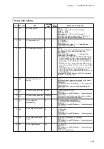
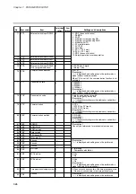
0 to 3600sec
When set to 0, operation continues regardless of outage time.
[Description:]
The HOLDmode is invoked when the outage is longer than set time.
The measurement of a power outage may vary by about 10 seconds.
0
C 43
43
Length of outage permitting
continuous operation
[Description:]
Ò-----Ó is displayed and setting cannot be performed.
----
C 44
44
Unused
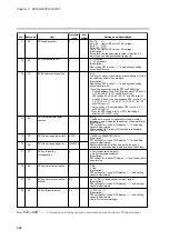
0: SP
1: PV
2: Deviation (DEV)
3: Manipulated variable (MV)
4: PV1
5: PV2
[Description:]
Ò-----Ó is displayed and setting cannot be performed on
model without auxiliary output.
0
C 45
45
Auxiliary output 1 type
Ð19999 to +20000 SPU (
C45
not equal to 3)
Ð1999.9 to +2000.0 SPU (
C45
set to 3)
[Description:]
Ò-----Ó is displayed and setting cannot be performed on
model without auxiliary output.
0 SPU
C 46
46
Auxiliary output 1 lower limit
(4mA)
10000SPU
C 47
47
Auxiliary output 1 upper limit
(20mA)
Ð5.0 to +105.0 %
0.0
C 32
32
Manipulated variable in READY mode
Содержание DCP550
Страница 1: ...EN1I 6186 Issue 13 04 08 DCP551 Mark ΙΙ Digital Control Programmer User s Manual www honeyvell energy ...
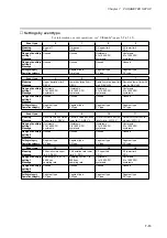
Страница 115: ...Chapter 7 PARAMETER SETUP Settings by event type For information on event operations see Events pages 5 5 to 5 15 7 13 ...
Страница 117: ...Chapter 7 PARAMETER SETUP 0 1 02 3 02 3 0 1 1 4 5 1 4 6 1 4 5 2 2 2 7 15 ...
Страница 119: ...Chapter 7 PARAMETER SETUP 0 11 2 2 3 3 7 17 ...
Страница 122: ...Chapter 7 PARAMETER SETUP d A5 tP A5 CP A5 rE A5 P A6 I A6 d A6 rE A6 CP A6 tP A6 P A7 I A7 d A7 rE A7 CP A7 tP A7 7 20 ...
Страница 209: ...Chapter 12 CALIBRATION Figure 12 11 Current Outputs 12 18 ...
Страница 229: ......
Страница 230: ...No CP UM 5024E ...

