


Chapter 4. WIRING
NOTE
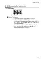
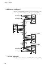
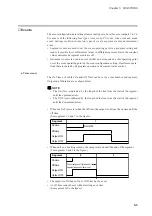
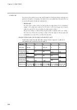
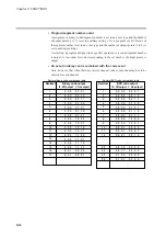
RS-232C connector signals (9 pins)
Example : IBM and compatibles
■
Connection to ST221
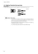
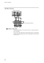
HANDLING PRECAUTIONS
• Attach 1/2W or greater terminating resistances of 150
Ω
±5% at each end of
the communications lines.
• The DCP551 operates as a master station when connected to an ST221 dur-
ing communications.
$ $ $ $! $"
5/
! " #
56 ,-#,+2
Pin No.
1
2
DCD
RxD
Name
¬
¬
3
TxD
®
4
DTR
®
5
GND
6
DSR
¬
7
RTS
®
8
CTS
¬
Signal direction
Host Instrument
4-17
Содержание DCP550
Страница 1: ...EN1I 6186 Issue 13 04 08 DCP551 Mark ΙΙ Digital Control Programmer User s Manual www honeyvell energy ...
Страница 115: ...Chapter 7 PARAMETER SETUP Settings by event type For information on event operations see Events pages 5 5 to 5 15 7 13 ...
Страница 117: ...Chapter 7 PARAMETER SETUP 0 1 02 3 02 3 0 1 1 4 5 1 4 6 1 4 5 2 2 2 7 15 ...
Страница 119: ...Chapter 7 PARAMETER SETUP 0 11 2 2 3 3 7 17 ...
Страница 122: ...Chapter 7 PARAMETER SETUP d A5 tP A5 CP A5 rE A5 P A6 I A6 d A6 rE A6 CP A6 tP A6 P A7 I A7 d A7 rE A7 CP A7 tP A7 7 20 ...
Страница 209: ...Chapter 12 CALIBRATION Figure 12 11 Current Outputs 12 18 ...
Страница 229: ......
Страница 230: ...No CP UM 5024E ...