Chapter 7. PARAMETER SETUP
■
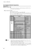
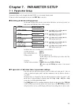
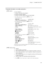
Modifying individual items and exiting the setting mode
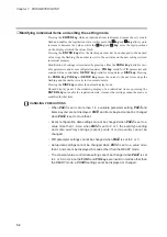
Pressing the
ENTER key
while an individual item is displayed causes the set value to
flash and enables the registration state. At this point, the
↑↑
key
and
↓↓
key
allow you to
increase or decrease the values, while the
←
←
key
and
→
→
key
move the digit positions
on the display at which the values flash.
Pressing the
ENTER key
after the flashing number has been changed to the desired
value stops the flashing, the number reverts to the on state and the new setting is stored
in internal memory.
Modification of settings is terminated by pressing either the
PARA key
(valid for vari-
able parameters and event configuration data),
PID key
(valid for PID parameters and
constant value control data),
SETUP key
(valid for setup data) or
DISP key
. Pressing
the
PARA key
,
PID key
or
SETUP key
moves the cursor to the next item stops the
flashing and the number reverts to its normal on state.
Pressing the
DISP key
enables the normal display mode.
Should display panel 2 showcduring display of an individual item or pressing the
ENTER key
not enable the registration state, it means that settings cannot be made or
modified for that item.
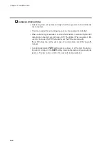
HANDLING PRECAUTIONS
• When
PA01
is set to more than 1 in a variable parameter setting,
PA03
and
items beyond are not displayed.
PA03
and items beyond cannot be changed
when
PA02
is set to more than 1.
• Event configuration data settings cannot be changed when
PA02
is set to a
value more than 1. Also, when
PA02
is set to 0 or 1, the event type setting
and some auxiliary settings (output points of code events) cannot be
changed.
• PID parameter settings cannot be changed when
PA02
is set to 4 or 5.
• Setup data settings cannot be changed when
PA02
is set to a value more
than 1 and cannot be displayed in modes other than the READY mode.
• The constant value control data setting cannot be changed when
PA02
is set
to 4 or 5. And, since the
FUNC
and
PID keys
are invalid in modes other than
the READY mode, a
ConSt
setting cannot be displayed or changed.
7-2
Содержание DCP550
Страница 1: ...EN1I 6186 Issue 13 04 08 DCP551 Mark ΙΙ Digital Control Programmer User s Manual www honeyvell energy ...
Страница 115: ...Chapter 7 PARAMETER SETUP Settings by event type For information on event operations see Events pages 5 5 to 5 15 7 13 ...
Страница 117: ...Chapter 7 PARAMETER SETUP 0 1 02 3 02 3 0 1 1 4 5 1 4 6 1 4 5 2 2 2 7 15 ...
Страница 119: ...Chapter 7 PARAMETER SETUP 0 11 2 2 3 3 7 17 ...
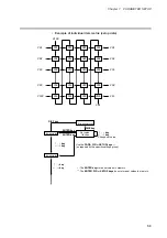
Страница 122: ...Chapter 7 PARAMETER SETUP d A5 tP A5 CP A5 rE A5 P A6 I A6 d A6 rE A6 CP A6 tP A6 P A7 I A7 d A7 rE A7 CP A7 tP A7 7 20 ...
Страница 209: ...Chapter 12 CALIBRATION Figure 12 11 Current Outputs 12 18 ...
Страница 229: ......
Страница 230: ...No CP UM 5024E ...

