Chapter 2. NAMES AND FUNCTIONS OF PARTS
2-3
●
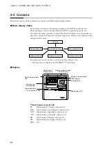
Display panel 1
Indicates PV and other data in basic display status.
Indicates item codes in parameter setting status.
Indicates set values and item codes in program setting status.
●
Display panel 2
Indicates SP, time, output and other data in basic display status.
Indicates set values in parameter setting status.
Indicates set values in program setting status.
●
Message display
Indicates output graph, deviation graph, running progress graph, event status, pro-
gram tag and other data in basic display status.
Displays reference messages in parameter setting status.
Displays tag settings and reference messages in program setting status.
Indicates selected operation and operation results during memory card operation.
●
Program number display
Indicates a selected program number in basic display status.
Indicates a set program number in program setting status.
Off during constant value control.
Indicates the alarm code “
AL
” when an alarm occurs in basic display status.
●
Segment number display
Indicates a selected segment number in basic display status.
Indicates a set segment number in program setting status.
Off during constant value control.
Indicates an alarm code number when an alarm occurs in basic display status.
●
Mode display LED
RUN, HLD
: Indicates the RUN, HOLD, FAST, END, and READY FAST modes
(see the table below).
MAN
: Lights in MANUAL mode. Off in AUTO mode.
PRG
: Lights in program setting status, otherwise off.
AT
: Flickers during auto tuning execution, otherwise off.
BAT
: Flickers when battery voltage is too low, otherwise off.
EG1, EG2
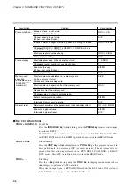
: Lights when an event number output set by
PA41
or
PA42
is set to
ON setting. Off when set to OFF.
●
Profile display
Indicates the rising, soaking, and falling trends of a program pattern.
Flickers during G.SOAK wait and lights continuously after power on.
Mode
LED
RUN
HLD
OFF
OFF
READY
Lights
OFF
RUN
OFF
Lights
HOLD
Flicker
OFF
FAST
OFF
Flickers
END
Lights
Lights
READY FAST
Содержание DCP550
Страница 1: ...EN1I 6186 Issue 13 04 08 DCP551 Mark ΙΙ Digital Control Programmer User s Manual www honeyvell energy ...
Страница 115: ...Chapter 7 PARAMETER SETUP Settings by event type For information on event operations see Events pages 5 5 to 5 15 7 13 ...
Страница 117: ...Chapter 7 PARAMETER SETUP 0 1 02 3 02 3 0 1 1 4 5 1 4 6 1 4 5 2 2 2 7 15 ...
Страница 119: ...Chapter 7 PARAMETER SETUP 0 11 2 2 3 3 7 17 ...
Страница 122: ...Chapter 7 PARAMETER SETUP d A5 tP A5 CP A5 rE A5 P A6 I A6 d A6 rE A6 CP A6 tP A6 P A7 I A7 d A7 rE A7 CP A7 tP A7 7 20 ...
Страница 209: ...Chapter 12 CALIBRATION Figure 12 11 Current Outputs 12 18 ...
Страница 229: ......
Страница 230: ...No CP UM 5024E ...

