


Chapter 7. PARAMETER SETUP
■
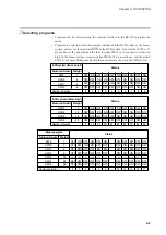
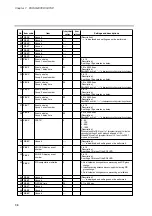
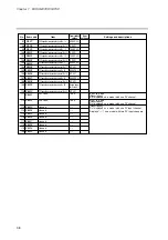
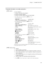
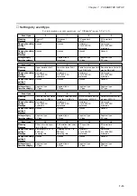
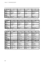
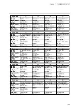
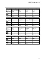
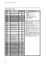
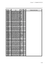
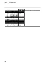
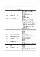
Detailed information on variable parameters
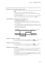
●
PA01
(keylock)
0: keylock disabled
1: display of setup data setting disabled
2: display of all settings disabled
3: display of all settings disabled. Operation keys disabled
• The following keys are disabled when
PA01
is set to 1.
Normal display mode:
SETUP key
(setup data setting)
FUNC + CLR + MESSAGE keys
(general reset)
• The following keys are disabled when
PA01
is set to 2.
Normal display mode:
SETUP key
(setup data setting)
FUNC + CLR + MESSAGE keys
(general reset)
FUNC + PARA keys
(event configuration data setting)
PID key
(PID parameter setting/constant value con-
trol data setting)
FUNC + PID keys
(constant value control data setting)
FUNC + PROG keys
(program setting)
↑↑
+ PROG keys
(program copy)
LOAD key
(memory card load)
SAVE key
(memory card save)
• The following keys are disabled when
PA01
is set to 3 or to 2.
Normal display mode:
PROG key
(program selection)
RUN/HOLD key
(RUN operation/HOLD operation)
PROG + RUN/HOLD keys
(RESET operation)
PROG + DISP keys
(ADV operation)
FUNC +
→
→
keys
(FAST operation)
A/M key
(AUTO operation/MANUAL operation)
AT key
(AT start, AT cancel)
Note, however, that in the normal display mode in MANUAL mode MV (controller)
and SP (programmer) can be changed.
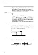
●
PA02
(memory protect)
0 : disabled
1 : program settings are protected
2 : setup, variable parameters and event configuration settings are protected
3 : setup, variable parameters, event configuration settings and program set-
tings are protected
4 : setup, variable parameters, event configuration settings and PID parameter
settings are protected
5 : program settings and all parameter settings are protected
• When
PA02
is set to ≠ 0 (protect on), a general reset cannot be performed.
7-9
Содержание DCP550
Страница 1: ...EN1I 6186 Issue 13 04 08 DCP551 Mark ΙΙ Digital Control Programmer User s Manual www honeyvell energy ...
Страница 115: ...Chapter 7 PARAMETER SETUP Settings by event type For information on event operations see Events pages 5 5 to 5 15 7 13 ...
Страница 117: ...Chapter 7 PARAMETER SETUP 0 1 02 3 02 3 0 1 1 4 5 1 4 6 1 4 5 2 2 2 7 15 ...
Страница 119: ...Chapter 7 PARAMETER SETUP 0 11 2 2 3 3 7 17 ...
Страница 122: ...Chapter 7 PARAMETER SETUP d A5 tP A5 CP A5 rE A5 P A6 I A6 d A6 rE A6 CP A6 tP A6 P A7 I A7 d A7 rE A7 CP A7 tP A7 7 20 ...
Страница 209: ...Chapter 12 CALIBRATION Figure 12 11 Current Outputs 12 18 ...
Страница 229: ......
Страница 230: ...No CP UM 5024E ...