Chapter 6. OPERATION
■
Read timing
●
SW1 to 8 timing
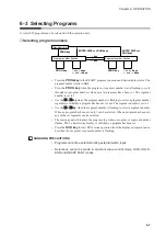
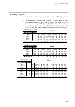
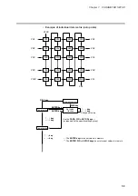
SW1 to 8 are read according to the timing in the figure shown below.
(1) When the input changes from OFF to ON, reading starts within less than 0.2 sec-
onds.
(2) When the input changes from ON to OFF, reading starts within less than 0.2 sec-
onds.
●
SW9 to 16 and RUN, FAST (READY FAST) timing
Selecting SW9 to 16 program numbers takes less than 0.4 seconds after a change in
input status.
Thus the following timings (1) to (4) must be observed during RUN operations. FAST
(READY FAST) operations should follow the same timings.
(1)Time from number selection to leading edge of the RUN signal : 0.4 seconds or more
(2)Time from the leading edge of the RUN signal to number selection hold : 0.2 seconds or more
(3)Time from RUN signal OFF to leading edge of RUN signal
: 0.2 seconds or more
(4)Time from leading edge of RUN signal to RUN signal ON hold : 0.2 seconds or more
(5)Time from entry of selected number to program number change
: 0.4 seconds or less
(6)Time from leading edge of RUN signal to start of RUN signal : 0.4 seconds or less
HANDLING PRECAUTIONS
To ensure correct operation, the above read timings should be regarded as min-
imum time settings in external switch operations.
State of numbers
not selected
(1)
(2)
State of selected numbers
State of numbers
not selected
(3)
(4)
(5)
(6)
Numbers not selected
Selected numbers
Program number
RUN signal
Selected program
number
(8-point input)
READY
Mode
RUN
External switch
input status
(1)
On reading
(2)
Off reading
6-11
Содержание DCP550
Страница 1: ...EN1I 6186 Issue 13 04 08 DCP551 Mark ΙΙ Digital Control Programmer User s Manual www honeyvell energy ...
Страница 115: ...Chapter 7 PARAMETER SETUP Settings by event type For information on event operations see Events pages 5 5 to 5 15 7 13 ...
Страница 117: ...Chapter 7 PARAMETER SETUP 0 1 02 3 02 3 0 1 1 4 5 1 4 6 1 4 5 2 2 2 7 15 ...
Страница 119: ...Chapter 7 PARAMETER SETUP 0 11 2 2 3 3 7 17 ...
Страница 122: ...Chapter 7 PARAMETER SETUP d A5 tP A5 CP A5 rE A5 P A6 I A6 d A6 rE A6 CP A6 tP A6 P A7 I A7 d A7 rE A7 CP A7 tP A7 7 20 ...
Страница 209: ...Chapter 12 CALIBRATION Figure 12 11 Current Outputs 12 18 ...
Страница 229: ......
Страница 230: ...No CP UM 5024E ...

