Chapter 5. FUNCTIONS
●
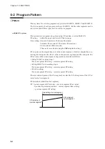
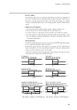
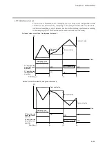
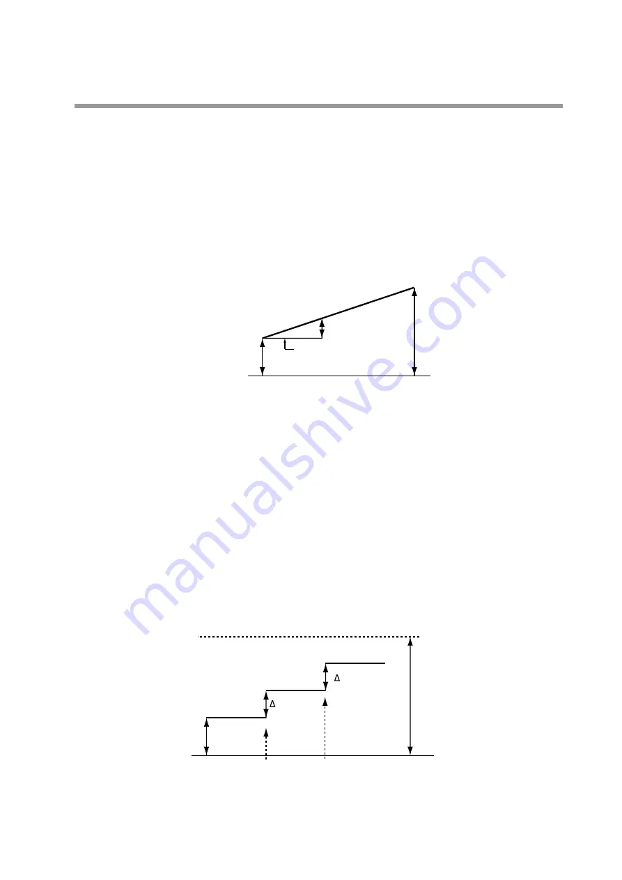
RAMP-T system (
θθ
setting)
In the RAMP-T system, a segment is set using SP and ramp
θ
(theta).
SP setting: within the upper and lower SP limiter range
θ
setting : 1 to 10000 (SPU/hour, SPU/min, SPU/sec)
(Time units are selected using the
C62
setup data setting.)
SP is a point on the elapsed time axis in the current segment which is an extended
straight line, the ramp set value of the current segment when the SP set value in the pre-
vious segment is the start point.
The end point is the point where this line reaches the SP setpoint of the current segment.
Note that the RAMP-T system cannot be used in the first segment.
SP calculation: SP =
θ
set value
×
segment elapsed time + previous segment SP.
●
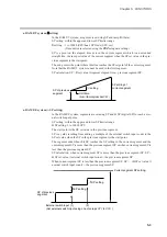
RAMP-E system (∆ SP setting)
In the RAMP-E system, segments are set using SP and
∆
SP (digital SP) for each exter-
nal switch input pulse.
SP setting: within the upper and lower SP limiter range
∆
SP setting: 1 to 10000 SPU
The start point is the SP set value in the previous segment.
SP is a value resulting from adding a multiple of the external switch input count to the
SP set value when the SP in the previous segment is the start point.
The segment ends when this SP reaches the SP setting in the current segment and the
current segment SP is more than the previous segment SP or when current segment SP is
less than the previous segment SP.
SP calculation: when current segment SP is more than the previous segment SP, SP =
∆
SP set value
×
external switch input count + the previous segment SP.
When current segment SP is less than the previous segment SP, SP = – (
∆
SP set value
×
exernal switch input count) + the previous segment SP.
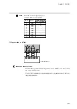
C71
C74
SP setting of
current segment
SP of previous
segment
Unit time
(Set unit time using setup data
C62
.)
setting
G
5-3
Содержание DCP550
Страница 1: ...EN1I 6186 Issue 13 04 08 DCP551 Mark ΙΙ Digital Control Programmer User s Manual www honeyvell energy ...
Страница 115: ...Chapter 7 PARAMETER SETUP Settings by event type For information on event operations see Events pages 5 5 to 5 15 7 13 ...
Страница 117: ...Chapter 7 PARAMETER SETUP 0 1 02 3 02 3 0 1 1 4 5 1 4 6 1 4 5 2 2 2 7 15 ...
Страница 119: ...Chapter 7 PARAMETER SETUP 0 11 2 2 3 3 7 17 ...
Страница 122: ...Chapter 7 PARAMETER SETUP d A5 tP A5 CP A5 rE A5 P A6 I A6 d A6 rE A6 CP A6 tP A6 P A7 I A7 d A7 rE A7 CP A7 tP A7 7 20 ...
Страница 209: ...Chapter 12 CALIBRATION Figure 12 11 Current Outputs 12 18 ...
Страница 229: ......
Страница 230: ...No CP UM 5024E ...


