


4-7 Control Output Connection ................................................................................ 4-9
■
Current output ................................................................................................ 4-9
■
Voltage output ................................................................................................ 4-9
■
Open collector output ..................................................................................... 4-9
4-8 Auxiliary Output (Output CH1, CH2) Connection............................................... 4-10
■
Auxiliary output CH1 connection .................................................................... 4-10
■
Auxiliary output CH2 connection .................................................................... 4-10
4-9 Event Output (Open Collector Output) Connection............................................ 4-11
4-10 External Switch Input Connection ...................................................................... 4-12
4-11 Communication Connection............................................................................... 4-13
■
RS-485 connection......................................................................................... 4-13
■
RS-232C connection ...................................................................................... 4-16
■
Connection to ST221 ..................................................................................... 4-17
4-12 Isolation Between Input and Output................................................................... 4-18
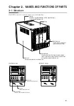
Chapter 5. FUNCTIONS
5-1 Data ................................................................................................................... 5-1
■
Data types ...................................................................................................... 5-1
5-2 Program Pattern................................................................................................. 5-2
■
Pattern............................................................................................................ 5-2
■
Events ............................................................................................................ 5-5
■
PID group selection........................................................................................ 5-16
■
Selection of output limiter group..................................................................... 5-16
■
G.SOAK (Guarantee soak) ............................................................................ 5-17
■
PV shift........................................................................................................... 5-18
■
Repeat............................................................................................................ 5-19
■
PV start .......................................................................................................... 5-20
■
Cycle .............................................................................................................. 5-21
■
Pattern link ..................................................................................................... 5-22
■
Tag ................................................................................................................. 5-23
5-3 Mode .................................................................................................................. 5-24
■
Mode types..................................................................................................... 5-24
■
Mode transitions............................................................................................. 5-26
■
Mode transition operations............................................................................. 5-27
■
Mode transition restrictions ............................................................................ 5-28
5-4 Controllers and programmers ............................................................................ 5-29
5-5 Input Process Functions .................................................................................... 5-30
■
PV input 1 channel model .............................................................................. 5-30
■
PV input 2 channel model .............................................................................. 5-31
■
Channel switching (PV input 2 channel model).............................................. 5-32
5-6 Output Processing Functions............................................................................. 5-37
■
Control output................................................................................................. 5-37
■
SP output ....................................................................................................... 5-39
■
Auxiliary output............................................................................................... 5-39
vii
Содержание DCP550
Страница 1: ...EN1I 6186 Issue 13 04 08 DCP551 Mark ΙΙ Digital Control Programmer User s Manual www honeyvell energy ...
Страница 115: ...Chapter 7 PARAMETER SETUP Settings by event type For information on event operations see Events pages 5 5 to 5 15 7 13 ...
Страница 117: ...Chapter 7 PARAMETER SETUP 0 1 02 3 02 3 0 1 1 4 5 1 4 6 1 4 5 2 2 2 7 15 ...
Страница 119: ...Chapter 7 PARAMETER SETUP 0 11 2 2 3 3 7 17 ...
Страница 122: ...Chapter 7 PARAMETER SETUP d A5 tP A5 CP A5 rE A5 P A6 I A6 d A6 rE A6 CP A6 tP A6 P A7 I A7 d A7 rE A7 CP A7 tP A7 7 20 ...
Страница 209: ...Chapter 12 CALIBRATION Figure 12 11 Current Outputs 12 18 ...
Страница 229: ......
Страница 230: ...No CP UM 5024E ...