


Chapter 7. PARAMETER SETUP
●
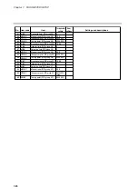
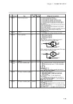
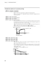
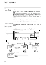
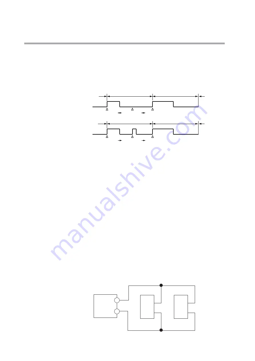
C93
(time proportional output system)
0:
Does not go on a second time off in time proportional cycle.
1:
Goes on a second time in time proportional cycle.
• This setting determines whether the output is to go on again after the result of a PID
computation has changed in a time proportional cycle (cycle time) and the output has
been turned off.
• The difference between the two settings is illustrated below.
●
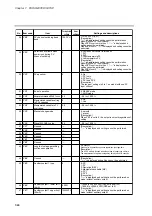
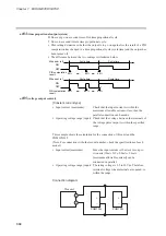
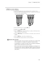
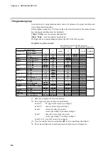
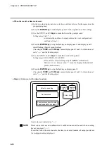
C95
(voltage output control)
[Constant current type]
• Input current (maximum):
Check that the input current is within the
maximum allowable current or less, then the
parallel connection can be made.
• Operating voltage range (input): Check that the voltage between the terminals of
the voltage pulse output is within the specified
range.
This example shows the calculation for the connection of this unit and the
PGM10N015.
(Note: For connection with other model number, check the specifications of each
model.)
• Input current(maximum):
Since the input current is 10mA or less, up to
two units (10mA X 2 = 20mA < 24mA
[maximum allowable current]) can be
connected in parallel.
• Operating voltage range (input): The rating voltage is 3.5 to 30Vdc. Therefore,
terminal voltage when terminals are opened, is
within the range.
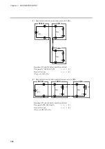
Connection diagram
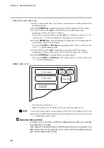
20%
65%
40%
OFF
ON
PID computation
result
Cycle time
Cycle time
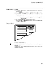
20%
65%
40%
OFF
ON
PID computation
result
Cycle time
Cycle time
When set to 0
When set to 1
7-30
This unit
+
–
+
–
PGM10N
+
–
PGM10N
Содержание DCP550
Страница 1: ...EN1I 6186 Issue 13 04 08 DCP551 Mark ΙΙ Digital Control Programmer User s Manual www honeyvell energy ...
Страница 115: ...Chapter 7 PARAMETER SETUP Settings by event type For information on event operations see Events pages 5 5 to 5 15 7 13 ...
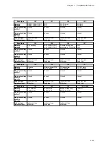
Страница 117: ...Chapter 7 PARAMETER SETUP 0 1 02 3 02 3 0 1 1 4 5 1 4 6 1 4 5 2 2 2 7 15 ...
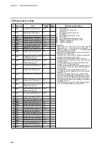
Страница 119: ...Chapter 7 PARAMETER SETUP 0 11 2 2 3 3 7 17 ...
Страница 122: ...Chapter 7 PARAMETER SETUP d A5 tP A5 CP A5 rE A5 P A6 I A6 d A6 rE A6 CP A6 tP A6 P A7 I A7 d A7 rE A7 CP A7 tP A7 7 20 ...
Страница 209: ...Chapter 12 CALIBRATION Figure 12 11 Current Outputs 12 18 ...
Страница 229: ......
Страница 230: ...No CP UM 5024E ...


