Chapter 5. FUNCTIONS
■
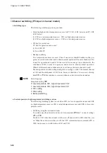
Channel switching (PV input 2 channel model)
●
Switching types
The following switching types are provided.
• Selecting high and low-temperature sensors for PV CH1 (CH1 below) and PV CH2
(CH2 below)
(1) CH1 is a low-temperature CH2 is a high-temperature sensor
(2) CH1 is a high-temperature CH2 is a low-temperature sensor
• CH tied for control use
PV tied for operation and control
(1) Tied CH1 PV
(2) Tied CH2 PV
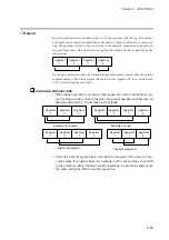
• Backup switching
Two temperature sensors are used. Thus if one sensor should breakdown, the pro-
gram can switch to the other and continue normal operation. The main channel (CH1)
is used for operation and control. In the event of an overrange (up or downscale), the
subchannel (CH2) is used for operation and control to ensure normal operation.
When both the main and subchannels are in overrange, the main channel is used.
The manipulated variable setting during this overrange is valid. The normal channel
is CH1 and the subchannel is CH2. Note, however, that when 7 is set in one of setup
data
C71
to
C74
, this situation is reversed when an external switch is turned on.
NOTE
Switching type
Setup data setting
C25
0: Low-temperature CH1, high-temperature CH2
1: Low-temperature CH2, high-temperature CH1
2: CH1 setting
3: CH2 setting
4: Backup switching
●
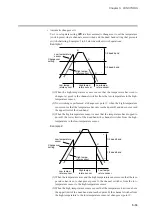
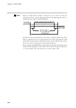
Low-temperature, high-temperature switching systems
The following switching system is used when CH1 is a low-temperature sensor and CH2
is a high-temperature sensor or CH1 is a high-temperature sensor and CH2 is a low-tem-
parature sensor.
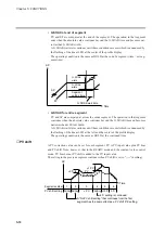
• Switching using the external switches
To switch using the external switches, set 0 in setup data
C26
and 7 in one of settings
C71
to
C74
.
Switch to CH1 when the external switches are off and switch to CH2 when they are
on. When the external switches are off, the CPL communications command (WS or
WB) can be used to switch between CH1 and CH2.
5-32
Содержание DCP550
Страница 1: ...EN1I 6186 Issue 13 04 08 DCP551 Mark ΙΙ Digital Control Programmer User s Manual www honeyvell energy ...
Страница 115: ...Chapter 7 PARAMETER SETUP Settings by event type For information on event operations see Events pages 5 5 to 5 15 7 13 ...
Страница 117: ...Chapter 7 PARAMETER SETUP 0 1 02 3 02 3 0 1 1 4 5 1 4 6 1 4 5 2 2 2 7 15 ...
Страница 119: ...Chapter 7 PARAMETER SETUP 0 11 2 2 3 3 7 17 ...
Страница 122: ...Chapter 7 PARAMETER SETUP d A5 tP A5 CP A5 rE A5 P A6 I A6 d A6 rE A6 CP A6 tP A6 P A7 I A7 d A7 rE A7 CP A7 tP A7 7 20 ...
Страница 209: ...Chapter 12 CALIBRATION Figure 12 11 Current Outputs 12 18 ...
Страница 229: ......
Страница 230: ...No CP UM 5024E ...

