Chapter 5. FUNCTIONS
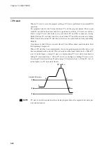
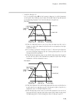
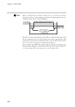
Example 3:
(1) When the high-temperature sensor senses that the temperature has risen to
changeover point A, the channel switches from the low-temperature to the high-
temperature sensor.
(2) When the high-temperature sensor senses that the temperature has risen above
the upper limit of the dead band and reached point B, the channel switches from
the high-temperature to the low-temperature sensor at changeover point C.
(3) No switching is performed at changeover point E when the high-temperature
sensor senses that the temperature has only dropped to point D and has not gone
below the upper limit of the dead band.
(4) When the high-temperature sensor senses that the temperature has reached point
F at the upper limit of the dead band, the channel switches from the high-temper-
ature to the low-temperature sensor at changeover point C.
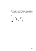
Example 4:
(1) When the high-temperature sensor senses that the temperature has risen to
changeover point A, the channel switches from the low-temperature to the high-
temperature sensor.
(2) When the high-temperature sensor senses that the temperature has risen above
the upper limit of the dead band and reached point B, the channel switches from
the high-temperature to the low-temperature sensor at changeover point C.
(3) When the high-temperature sensor senses that the temperature has dropped to
point D the lower limit of the dead band, the channel switches from the high-
temperature to the low-temperature sensor at changeover point E.
5-34
Содержание DCP550
Страница 1: ...EN1I 6186 Issue 13 04 08 DCP551 Mark ΙΙ Digital Control Programmer User s Manual www honeyvell energy ...
Страница 115: ...Chapter 7 PARAMETER SETUP Settings by event type For information on event operations see Events pages 5 5 to 5 15 7 13 ...
Страница 117: ...Chapter 7 PARAMETER SETUP 0 1 02 3 02 3 0 1 1 4 5 1 4 6 1 4 5 2 2 2 7 15 ...
Страница 119: ...Chapter 7 PARAMETER SETUP 0 11 2 2 3 3 7 17 ...
Страница 122: ...Chapter 7 PARAMETER SETUP d A5 tP A5 CP A5 rE A5 P A6 I A6 d A6 rE A6 CP A6 tP A6 P A7 I A7 d A7 rE A7 CP A7 tP A7 7 20 ...
Страница 209: ...Chapter 12 CALIBRATION Figure 12 11 Current Outputs 12 18 ...
Страница 229: ......
Страница 230: ...No CP UM 5024E ...

