


Chapter 7. PARAMETER SETUP
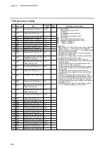
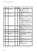
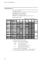
2 to 22mA
15
C 95
95
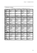
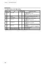
Voltage output control
[Description:]
Ò-----Ó is displayed and setting cannot be performed.
----
C 96
96
Unused
0 to 15
The backplate terminal is used when set to 0.
The loader jack is used for settings 1 to 15.
[Description:]
When set to 0, communications cannot be performed on model without
communications.
When set to 0, communications conditions are selected using
C76
to
C80
.
The communication address is used for settings 1 to 15.
4800bps, 8 bits, even parity, 1 stop bit
0
C 97
97
Communications port
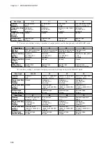
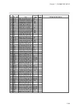
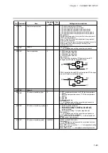
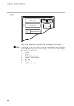
Ð20.00 to +20.00
[Description:]
Ò-----Ó is displayed and setting cannot be performed when
PV1 is not RTD or
C98
is not equal to 241.
----
C 99
99
PV1 zener barrier adjustment
0 to 255
[Description:]
A setting of0 is normally used.
0
C 98
98
Special function
Ð20.00 to +20.00
[Description:]
Ò-----Ó is displayed and setting cannot be performed when
PV2 is not RTD or
C98
is not equal to 241.
----
C100
100
PV2 zener barrier adjustment
7-27
Содержание DCP550
Страница 1: ...EN1I 6186 Issue 13 04 08 DCP551 Mark ΙΙ Digital Control Programmer User s Manual www honeyvell energy ...
Страница 115: ...Chapter 7 PARAMETER SETUP Settings by event type For information on event operations see Events pages 5 5 to 5 15 7 13 ...
Страница 117: ...Chapter 7 PARAMETER SETUP 0 1 02 3 02 3 0 1 1 4 5 1 4 6 1 4 5 2 2 2 7 15 ...
Страница 119: ...Chapter 7 PARAMETER SETUP 0 11 2 2 3 3 7 17 ...
Страница 122: ...Chapter 7 PARAMETER SETUP d A5 tP A5 CP A5 rE A5 P A6 I A6 d A6 rE A6 CP A6 tP A6 P A7 I A7 d A7 rE A7 CP A7 tP A7 7 20 ...
Страница 209: ...Chapter 12 CALIBRATION Figure 12 11 Current Outputs 12 18 ...
Страница 229: ......
Страница 230: ...No CP UM 5024E ...