Chapter 8. PROGRAM SETUP
■
Setting repeat items
(1) In the set value display state, move to the repeat item to be set for the segment on the
programming map.
(2) Press the
ENTER key
to make display panel 1 flash (registration of first setting).
(3) Use the
↑
,
↓
,
←
, and
→
keys
to make the first setting – setting the number of the
return segment.
Setting range: 0 to segment number in setting
(4) Press the
ENTER key
to stop the flashing on display panel 1 and display panel 2
starts flashing. (Start of second setting)
Note, however, that when the first setting is 0, “-----” is shown in the second panel
which does not flash.
(Pressing the
FUNC
and
CLR keys
causes display panel 1 and 2 to return to unset
state “
rP.0/
-----” and the flashing stops.)
(5) Use the
↑
,
↓
,
←
, and
→
keys
to make the second setting (repeat segment times).
Setting range: 1 to 10000
(6) Press the
ENTER key
to stop the flashing on display panel 2.
(Pressing the
FUNC
and
CLR keys
causes display panel 1 and 2 to return to unset
state “
rP.0/
-----” and the flashing stops.)
●
Display
• Unset values are indicated as “
rP.0/
-----”.
• When setup data
C59
is set to 1, a repeat item on the programming map is skipped
and not displayed.
NOTE
When the number of return segment is something other than 0, it uses a subfunction.
A subfunction cannot be used when a setting has not been made “
rP.0/
-----”.
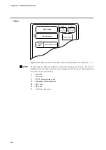
PROG
SEG
PROFILE
Program
number
Segment
number
Pattern trend
R E P E A T S E G M E N T
T I M E S
Set repeat count value
Set number of return segment
8-15
Содержание DCP550
Страница 1: ...EN1I 6186 Issue 13 04 08 DCP551 Mark ΙΙ Digital Control Programmer User s Manual www honeyvell energy ...
Страница 115: ...Chapter 7 PARAMETER SETUP Settings by event type For information on event operations see Events pages 5 5 to 5 15 7 13 ...
Страница 117: ...Chapter 7 PARAMETER SETUP 0 1 02 3 02 3 0 1 1 4 5 1 4 6 1 4 5 2 2 2 7 15 ...
Страница 119: ...Chapter 7 PARAMETER SETUP 0 11 2 2 3 3 7 17 ...
Страница 122: ...Chapter 7 PARAMETER SETUP d A5 tP A5 CP A5 rE A5 P A6 I A6 d A6 rE A6 CP A6 tP A6 P A7 I A7 d A7 rE A7 CP A7 tP A7 7 20 ...
Страница 209: ...Chapter 12 CALIBRATION Figure 12 11 Current Outputs 12 18 ...
Страница 229: ......
Страница 230: ...No CP UM 5024E ...

