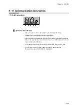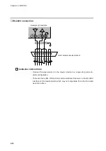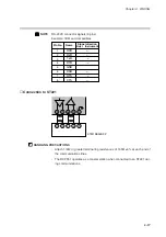
Chapter 4. WIRING
●
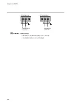
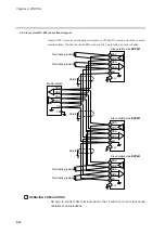
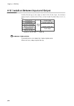
3-wire system RS-485 connection diagram
Attach 1/2W or greater terminating resistances of 150
Ω
±5% at each end of the commu-
nications lines. Ground the shield FGs at one end in one location, not at both ends.
When only three RS-485 terminals are provided, the areas designated with an asterisk
(*) are connected internally.
HANDLING PRECAUTIONS
• Be sure to connect SG terminals each other. Failure to do so might cause
unstable communications.
*
,+2##
,+2##
,+2##
*
4-15
Содержание DCP550
Страница 1: ...EN1I 6186 Issue 13 04 08 DCP551 Mark ΙΙ Digital Control Programmer User s Manual www honeyvell energy ...
Страница 115: ...Chapter 7 PARAMETER SETUP Settings by event type For information on event operations see Events pages 5 5 to 5 15 7 13 ...
Страница 117: ...Chapter 7 PARAMETER SETUP 0 1 02 3 02 3 0 1 1 4 5 1 4 6 1 4 5 2 2 2 7 15 ...
Страница 119: ...Chapter 7 PARAMETER SETUP 0 11 2 2 3 3 7 17 ...
Страница 122: ...Chapter 7 PARAMETER SETUP d A5 tP A5 CP A5 rE A5 P A6 I A6 d A6 rE A6 CP A6 tP A6 P A7 I A7 d A7 rE A7 CP A7 tP A7 7 20 ...
Страница 209: ...Chapter 12 CALIBRATION Figure 12 11 Current Outputs 12 18 ...
Страница 229: ......
Страница 230: ...No CP UM 5024E ...

