Chapter 7. PARAMETER SETUP
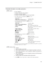
• When program settings are protected, it is not possible to copy programs or load pro-
grams from a memory card.
• When PID parameters are protected, Constant value control data is also protected.
• When settings are protected by setup data, variable parameters, event configurations
and PID parameters, they cannot be loaded from a memory card.
●
PA05
(program autoload)
0 : OFF
1 : ON
• This function is available on tne
DCP551E*****
model only.
• When
PA05
is set to 1 and a memory card is inserted and press
LOAD key
, display
panel 1 shows “
AUtO
”, display panel 2 shows “
LOAd
” and program file No. 1 is
read to program No. 1 in the DCP551. This operation is called “ program autoload”.
• A load operation other than a program autoload that is started using the
LOAD key
can only be performed when
PA05
is set to 0.
• A program autoload using the external switches can be performed when
PA05
is set
to 0 or 1.
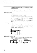
●
PA14
(manipulated variable deviation rate limit)
When output deviation (%) after a PID computation is larger than the set limit value, the
controller limits the output deviation both of the increase or decrease to the set value.
The following example shows the actual deviation change when the deviation limit is set
to 0.5% and the manipulated variable changes from 20% to 22%. When the set value is
0.5% per 0.1 sec, the output becomes 22% after 0.4 sec.
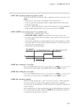
●
PA16
(ON-OFF control differential)
When the PID group number is set to ON-OFF or
P
is set to 0.0, ON-OFF control is on
and a value for the differential between the two operations is set.
%
t
t + 0.1 t + 0.2 t + 0.3 t + 0.4
20
21
22
Sec.
7-10
Содержание DCP550
Страница 1: ...EN1I 6186 Issue 13 04 08 DCP551 Mark ΙΙ Digital Control Programmer User s Manual www honeyvell energy ...
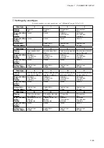
Страница 115: ...Chapter 7 PARAMETER SETUP Settings by event type For information on event operations see Events pages 5 5 to 5 15 7 13 ...
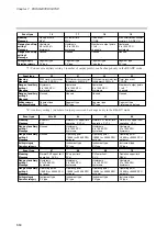
Страница 117: ...Chapter 7 PARAMETER SETUP 0 1 02 3 02 3 0 1 1 4 5 1 4 6 1 4 5 2 2 2 7 15 ...
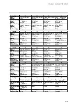
Страница 119: ...Chapter 7 PARAMETER SETUP 0 11 2 2 3 3 7 17 ...
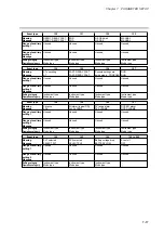
Страница 122: ...Chapter 7 PARAMETER SETUP d A5 tP A5 CP A5 rE A5 P A6 I A6 d A6 rE A6 CP A6 tP A6 P A7 I A7 d A7 rE A7 CP A7 tP A7 7 20 ...
Страница 209: ...Chapter 12 CALIBRATION Figure 12 11 Current Outputs 12 18 ...
Страница 229: ......
Страница 230: ...No CP UM 5024E ...


